Plate glass direction conversion device

A flat glass, direction conversion technology, applied in glass cutting device, glass forming, glass re-molding and other directions, can solve the problems of complex structure, increased contact area, difficult to apply to production lines, etc., to achieve simplification of structure, power and The effect of structure miniaturization

Inactive Publication Date: 2007-01-10
TAE SUNG ENG
View PDF0 Cites 23 Cited by
  • Summary
  • Abstract
  • Description
  • Claims
  • Application Information

AI Technical Summary

Problems solved by technology

[0004] However, in the above-mentioned prior art flat glass direction changing device, in order to be able to bear the load of the flat glass, a plurality of rollers must be prepared, so the contact area between the flat glass and the rollers is increased, which not only causes damage to the surface of the flat glass The probability increases, and the overall structure of the direction changing device becomes complicated due to the above-mentioned multiple rollers
Furthermore, in order to pivotally rotate the flat glass, it is necessary to rotate the whole of the heavy roller transfer machine as a pivot, so it is required to increase the size of the rotating device such as a drive motor.
In addition, in order to continuously improve the yield, the plate glass becomes larger and heavier, and the plate glass transfer device with rotating equipment and the like becomes larger and rigidity must also be increased. As a result, the structure is complicated and the manufacturing cost is increased. rising, creating problems that are difficult to apply to production lines

Method used


Image

  • Plate glass direction conversion device
  • Plate glass direction conversion device
  • Plate glass direction conversion device

Examples


Embodiment Construction

[0059] Hereinafter, a preferred embodiment of the present invention will be described in detail based on the drawings.

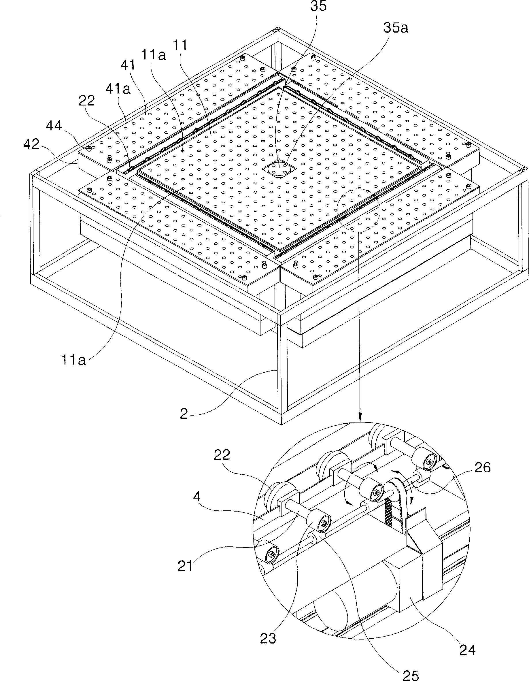
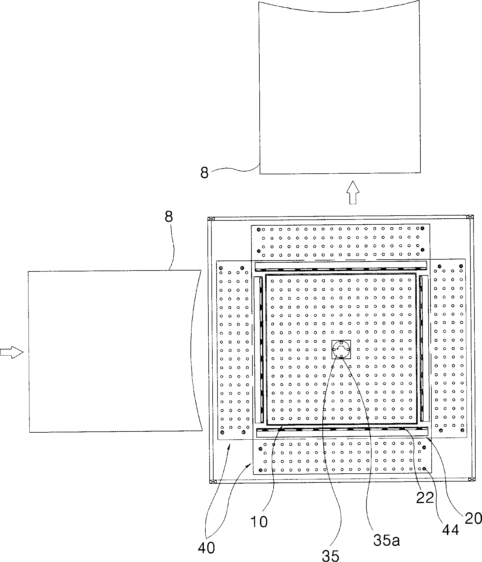
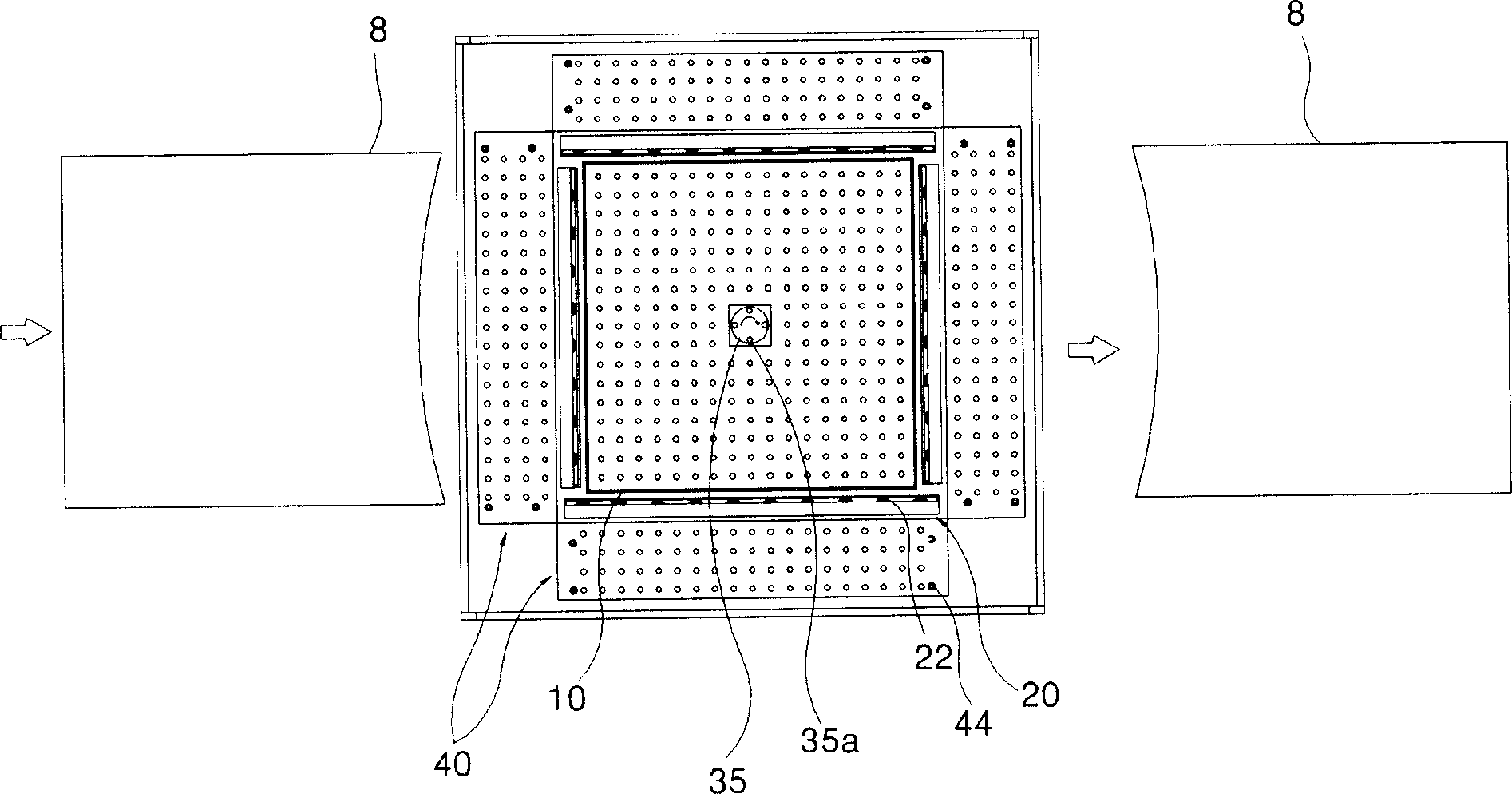
[0060] Such as Figure 1 to Figure 6 As shown, the structure of the direction changing device for plate glass of the present invention includes: an air ejector 10 for air-floating the plate glass 8 on the upper surface of the main frame 2; and a roller transfer machine 20 provided on the air ejector 10 adjacent to the outer circumferential surface; the rotating machine 30 is arranged in the center of the air ejector 10, so that the plate glass 8 loaded on the roller conveyor 30 rotates in situ.

[0061] The above-mentioned main frame 2 is a frame type used to support the roller support table 4 on its upper part; wheels (not shown) for transferring the main frame 2 to a specific place are provided at the lower end of each corner; and while being fixed to the desired position , A leveler (not shown) for maintaining the level of the main frame 2 is provided.

[0062...


PUM


Abstract

A direction changing device for flat glass minimizes the load on the flat glass by floating in the air, so that the flat glass is rotated in place and transferred in a specified direction. The flat glass direction changing device of the present invention comprises: an air ejector, comprising an air chamber and a fan box, the air chamber has an ejection plate for the air to float the flat glass, and the fan box is provided with an air jet fan for supplying air to the air chamber The roller transfer machine is arranged on the adjacent part of the outer peripheral surface of the air ejector, and has a plurality of rollers for transferring the flat glass in a prescribed direction; the rotary machine is arranged in the central part of the air ejector, so that the The flat glass is rotated in place. In the state of the flat glass floating in the air, the shaft rotates and transfers the flat glass, which not only minimizes the contact area between the flat glass and the roller and reduces the surface damage of the flat glass, but also simplifies the structure of the direction changing device regardless of the size of the flat glass , thereby miniaturizing the power and structure of the rotating equipment.

Description

Technical field [0001] The present invention relates to a direction switching device for plate glass, and in particular to a direction switching device for plate glass that minimizes the load of the plate glass by floating in the air, and can rotate the plate glass in this state and transfer it in a predetermined direction. Background technique [0002] Generally, the direction switching device as a plate glass can be divided into: a steering method that causes the plate glass to be sent to the worktable to travel in the direction of travel, or to change the direction in a right-angle direction to transfer; and to make the plate to be sent to the worktable. The glass travels in the direction of travel, or rotates in the original place, and then moves in the specified direction. [0003] Among such conversion devices, the above-mentioned turning type plate glass direction conversion device can only convert the direction of travel of the plate glass sent to the worktable at a right...

Claims


Application Information

Patent Timeline
Patent Type & Authority Applications(China)
IPC IPC(8): C03B35/24
CPCY02P40/57B29C63/02B65G47/91B65G49/067B65G53/00C03B23/03C03B23/0357C03B25/025C03B33/0235
Inventor 郑孝才李沃基
Owner TAE SUNG ENG
Why Eureka
Try Eureka