Blade fastening having safety device for turbine blades

a safety device and blade technology, applied in the direction of liquid fuel engines, vessel construction, marine propulsion, etc., can solve the problems of almost unavoidable turbine blade vibrating despite, and achieve the effect of avoiding unwanted loosening of the clamping pi

Inactive Publication Date: 2012-07-12
SIEMENS AG
View PDF1 Cites 7 Cited by
  • Summary
  • Abstract
  • Description
  • Claims
  • Application Information

AI Technical Summary

Benefits of technology

[0014]In order to avoid an unwanted loosening of the clamping piece, use is made of a locking element which is designed for locking the clamping piece. To this end, the clamping piece is designed as a locking plate and is arranged between the clamping piece and the rotor. By bending over the locking plate on the edge of the clamping piece, a displacement of the clamping piece is avoided, wherein at the same time the locking plate has to be arranged in a corresponding groove in the rotor.

Problems solved by technology

However, it is almost unavoidable that the turbine blade vibrates despite root fastening.

Method used


Image

  • Blade fastening having safety device for turbine blades
  • Blade fastening having safety device for turbine blades
  • Blade fastening having safety device for turbine blades

Examples


Embodiment Construction

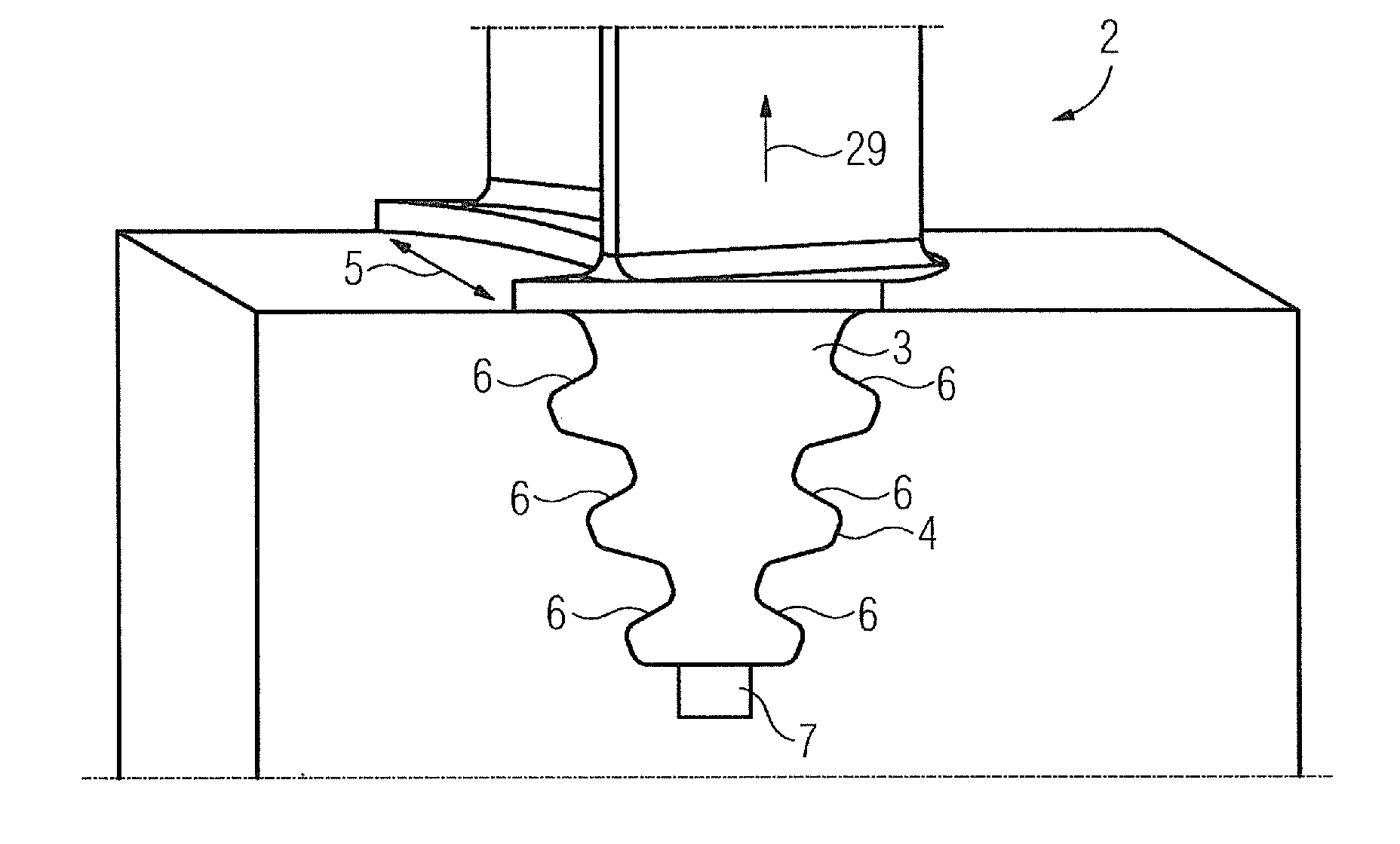
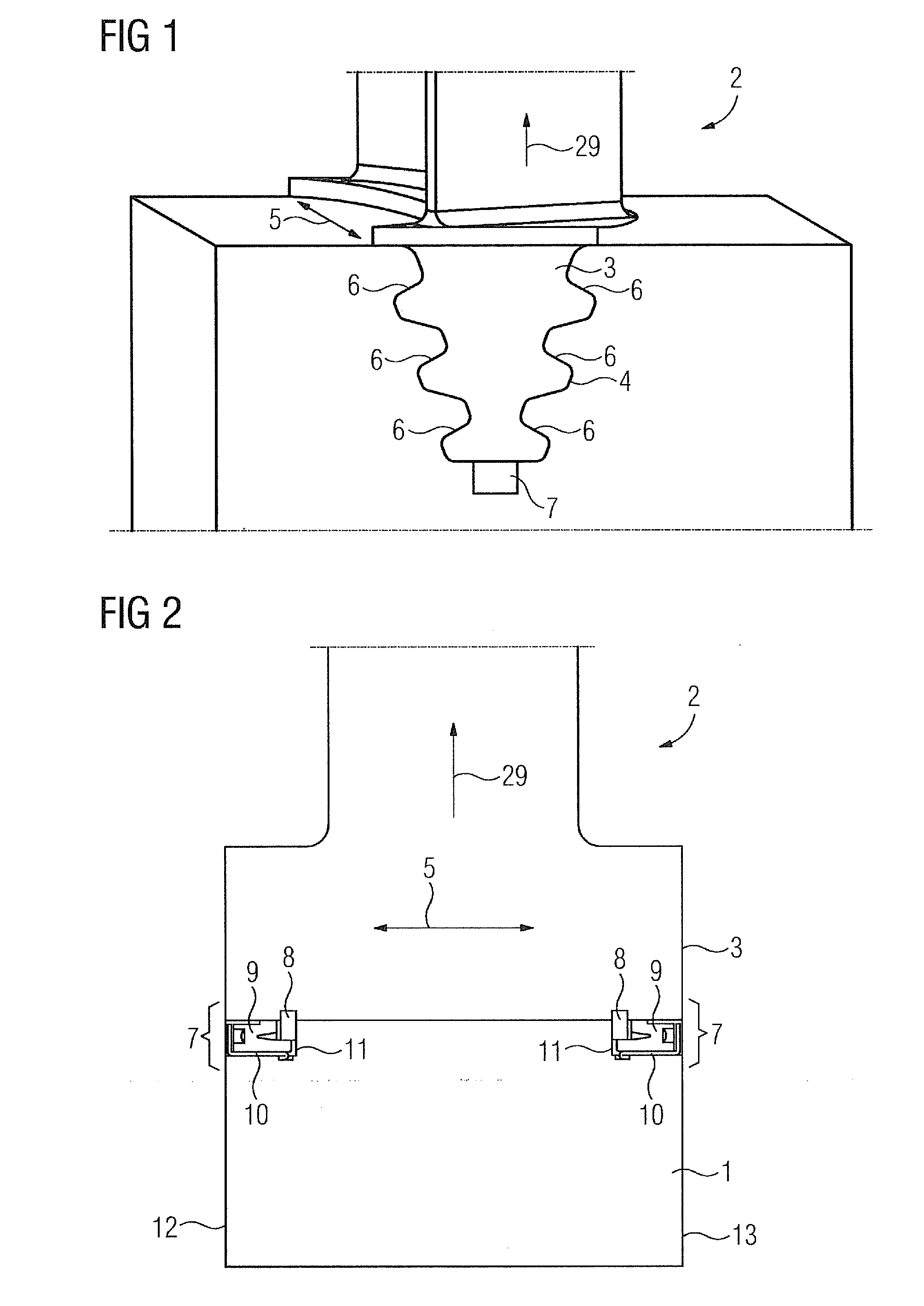
[0024]FIG. 1 shows a side view of a part of a rotor 1 with an installed turbine blade 2. The turbine blade 2 has a turbine blade root 3 which is fitted into a corresponding blade groove 4. The turbine blade 2 is inserted into the blade groove 4 in the axial direction 5. The blade groove 4 is designed as a fir-tree blade groove and comprises a plurality of bearing flanks 6.

[0025]The turbine blade 2 is locked in the blade groove 4 both in the axial direction 5 and in the radial direction 29. The radial direction 29 basically corresponds to the longitudinal orientation of the turbine blade 2 and the axial direction 5 basically corresponds to the rotational axis, which is not shown in more detail in FIG. 1.

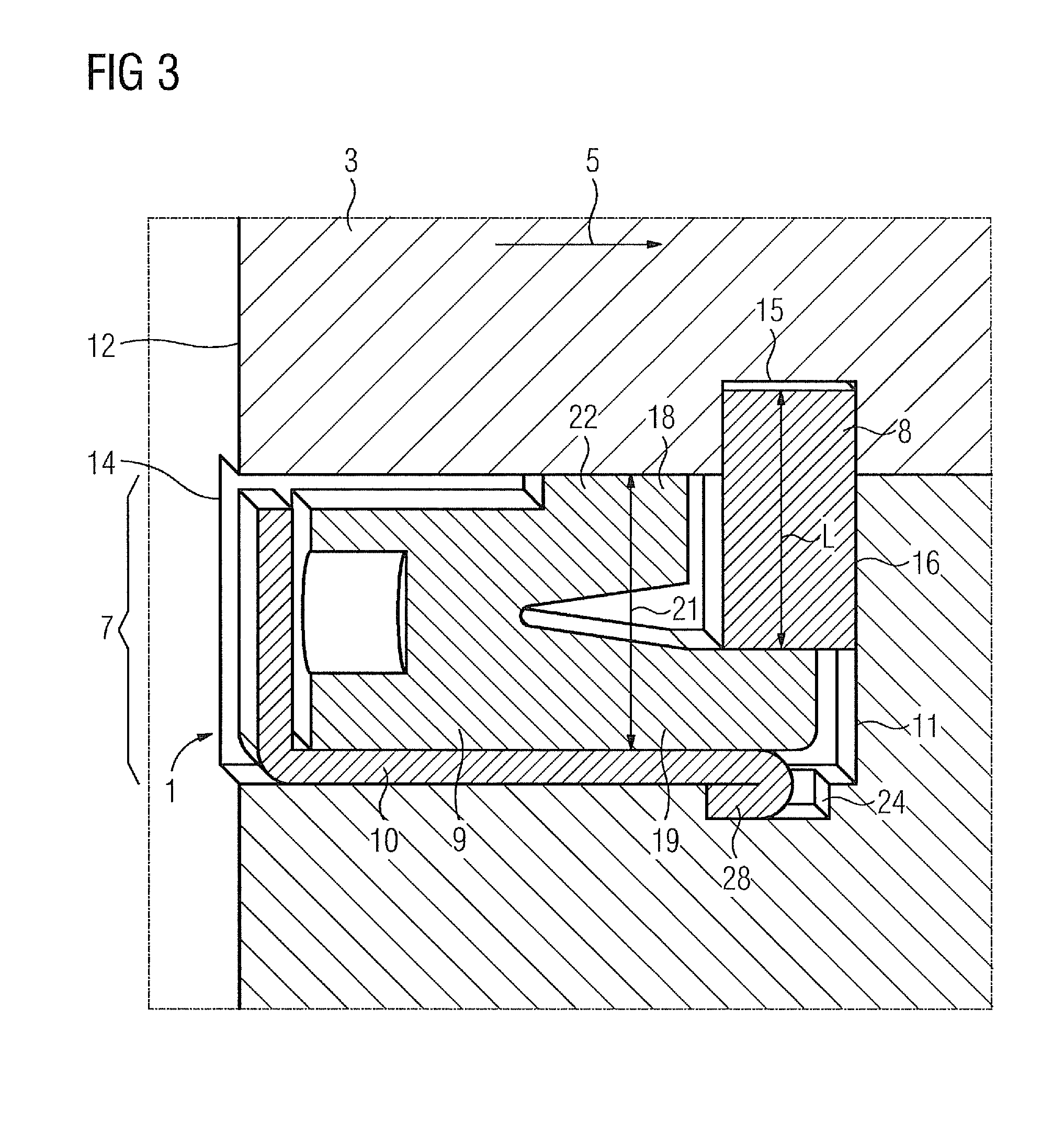
[0026]For locking the turbine blade 2, a locking device 7, which is arranged beneath the turbine blade root 3, is implemented. The turbine blade root 3 is designed in this case in such a way that this is fitted into the blade groove 4, i.e. can basically move in the axial direction 5....


PUM


Abstract

A safety device for a turbine blade is provided. The safety device includes a shear pin, a clamping piece and a securing element, wherein the shear pin is arranged in a corresponding bore in the turbine blade foot and the clamping piece is designed having an upper limb and a lower limb, wherein the clamping piece exerts a radial force on the turbine blade foot for radial safeguarding.

Description

CROSS REFERENCE TO RELATED APPLICATIONS[0001]This application is the US National Stage of International Application No. PCT / EP2010 / 063701, filed Sep. 17, 2010 and claims the benefit thereof. The International Application claims the benefits of European Patent Office application No. 09011885.2 EP filed Sep. 17, 2009. All of the applications are incorporated by reference herein in their entirety.FIELD OF INVENTION[0002]The invention relates to a rotor comprising at least one turbine blade and a locking device for the axial and radial locking of the turbine blade, wherein the rotor comprises a blade groove and the turbine blade comprises a turbine blade root, wherein the blade groove and the turbine blade root are designed in such a way that the turbine blade root is fitted in the blade groove.BACKGROUND OF INVENTION[0003]Blade fastenings are usually used for the fastening of rotor blades on a rotor of a turbomachine, especially a steam turbine. As a result of the comparatively fast ro...

Claims


Application Information

Patent Timeline
Patent Type & Authority Applications(United States)
IPC IPC(8): F01D5/32
CPCF01D5/323F05D2260/30F05B2260/3011
Inventor HELMIS, THOMASSTUER, HEINRICH
Owner SIEMENS AG
Why Eureka
Try Eureka