Radio communication system, radio communication method, radio transmitter and radio receiver using plurality of antennas

一种无线电接收机、无线电的技术,应用在无线电传输系统、分集/多天线系统、传输系统等方向,能够解决传输速率(吞吐量下降等问题

Inactive Publication Date: 2007-01-10
FUJITSU LTD
View PDF3 Cites 12 Cited by
  • Summary
  • Abstract
  • Description
  • Claims
  • Application Information

AI Technical Summary

Problems solved by technology

[0023] However, this will cause a decrease in the transmission rate (throughput), and requires information on the added pilot signal and processing related to it

Method used


Image

  • Radio communication system, radio communication method, radio transmitter and radio receiver using plurality of antennas
  • Radio communication system, radio communication method, radio transmitter and radio receiver using plurality of antennas
  • Radio communication system, radio communication method, radio transmitter and radio receiver using plurality of antennas

Examples


specific example 1

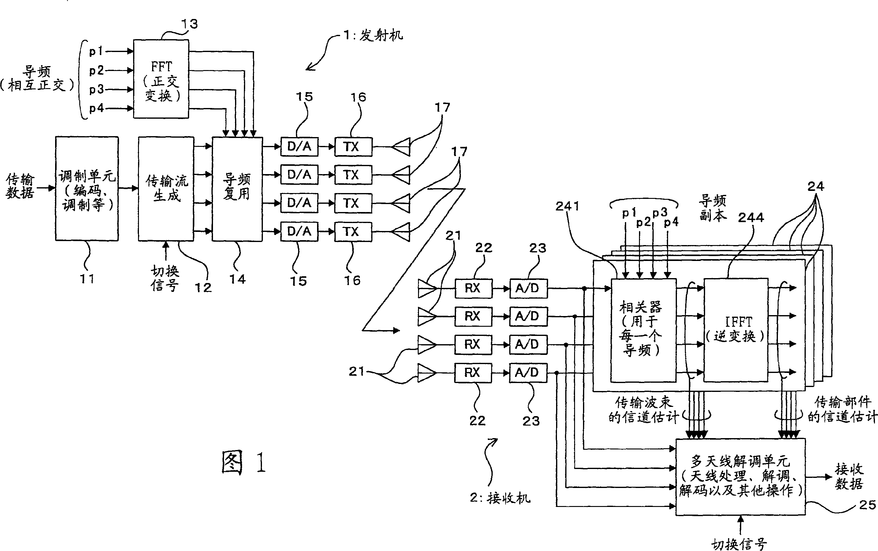
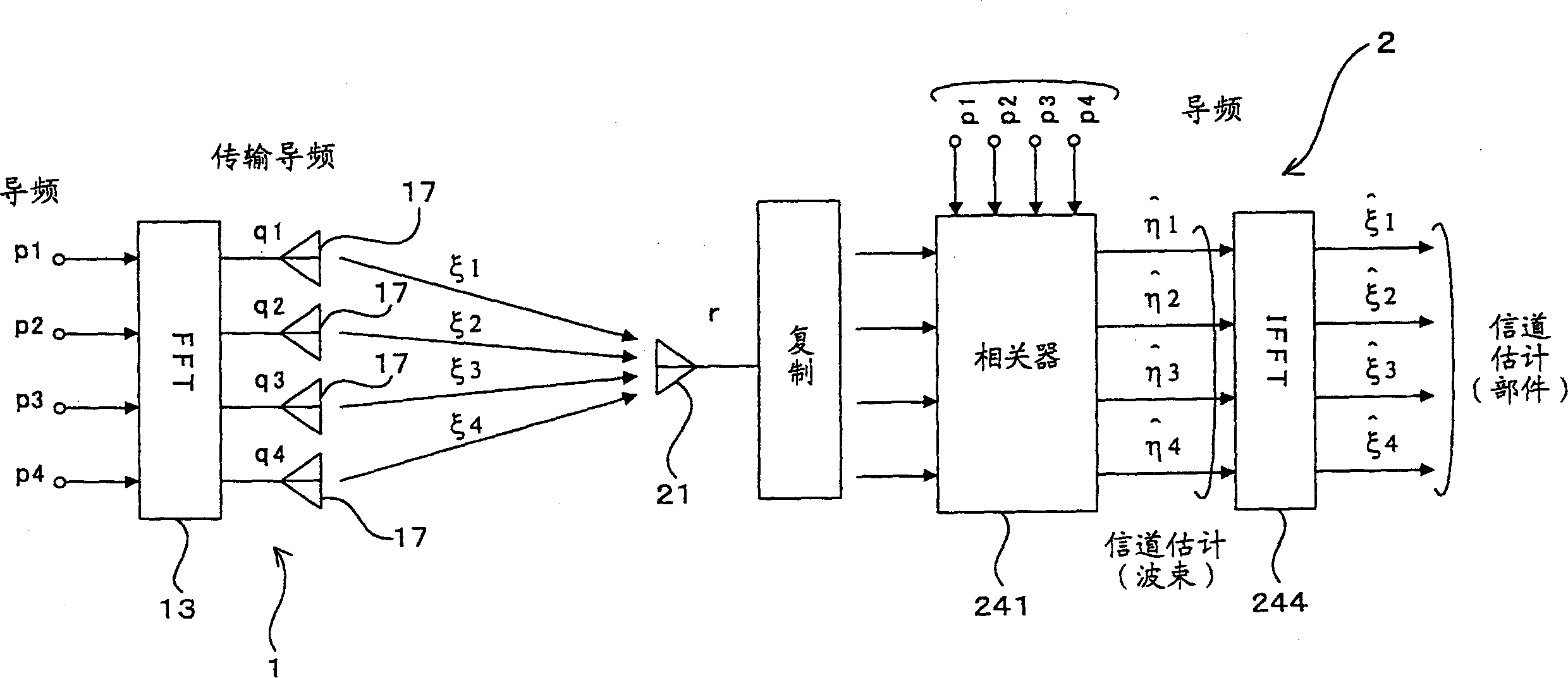
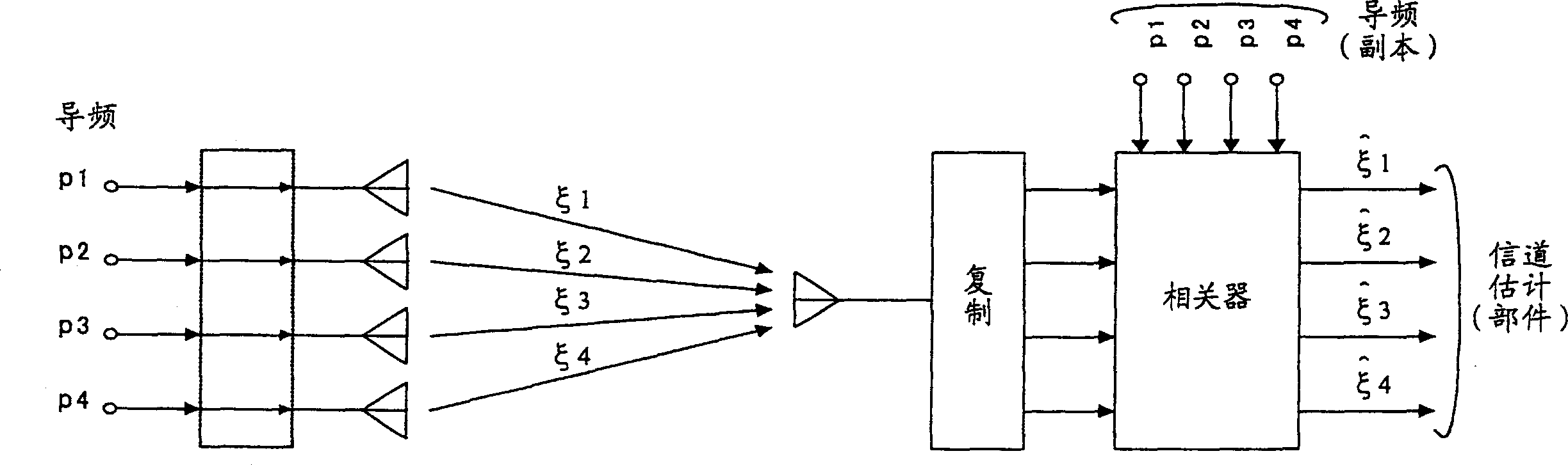
[0098] [B] Specific example 1 (MIMO / AAA transmitter-receiver structure)

[0099] In addition, we will refer to Figure 4 with 5 Let's describe the detailed structure of the transmitter-receiver that can switch between the MIMO mode and the AAA mode. Figure 4 Shows the detailed structure of transmitter 1, Figure 5 The detailed structure of the receiver 2 is shown.

[0100] (B1) Transmitter 1

[0101] Such as Figure 4 As shown in more detail, the transmitter 1 includes an encoder 111 and a modulator 112 as components of the modulation unit 11, and includes a beamforming unit (beamformer) 121 as a component of the transmission stream generating unit 12 , Serial-to-parallel converter 122 and switch 123. in Figure 4 Unless otherwise specified, other components marked with the same reference numerals as those used above are the same as the above-mentioned components or correspond to the above-mentioned components.

[0102] In this example, in the transmitter 1, the encoder 111 const...

specific example 2

[0135] [C] Specific example 2 (application of different types of receivers)

[0136] As mentioned above, in the case that the transmitter 1 can switch between MIMO and AAA with a four-antenna structure, many types can be applied to, for example, Figure 6 The radio communication system shown is used as the receiver 2.

[0137] In other words, the receiver 2G with a single antenna structure, the receiver 2D with a dual antenna structure dedicated to the MIMO mode, the receiver 2A with a four antenna structure dedicated to the MIMO mode, and the receiver 2F with a dual antenna structure dedicated to the AAA mode. , Receiver 2C with a four-antenna structure dedicated to AAA mode, Receiver 2E with a dual-antenna structure that can switch between MIMO and AAA, Receiver 2B with a four-antenna structure that can switch between MIMO and AAA, and other receivers The machines are all applicable.

[0138] In this case, regardless of the number of antennas and the circuit arrangement of the r...

specific example 3

[0142] [D] Specific example 3 (application mode for radio communication system)

[0143] Although the above-mentioned specific examples 1 and 2 refer to the structures of the transmitter 1 and the receiver 2 (2A to 2G), in this specific example 3, the mode of application of the radio communication system will be described. Figure 7 with Figure 8 It is an illustration of an application example of a radio communication system (mobile communication system). The case of downlink data transmission will be described here. In other words, the base station side will be used as the transmitter 1, and the terminal side will be used as the receiver 2.

[0144] (D1) Figure 7 Shows a system structure designed to use the MIMO mode and the AAA mode according to the application environment.

[0145] in Figure 7 Among them, three adjacent cells 100 are formed by three base stations (transmitters) 1A, 1B, and 1C adjacent to each other. In addition, an isolated cell 200 in another area relative ...


PUM


Abstract

A radio transmitter (1) includes a transmission data producing unit (12), an orthogonal transformation unit(13) carrying out an orthogonal transformation on pilot signals having orthogonal relation to each other between transmission antennas (17) and a pilot multiplexing unit (14) multiplexing the pilot signals and transmission data. A radio receiver (2) includes a channel estimation unit (24) obtaining a channel estimate of a directive multibeam for each of reception antennas (21), an inverse transformation unit (244) carrying out an inverse transformation of the orthogonal transformation on the obtained channel estimate and a received signal processing unit (25) selectively conducting first processing based on the beam channel estimate in the first mode or second processing based on the channel estimate obtained by the inverse transformation unit (244) in the second mode. This commonizes a common pilot for MIMO (second mode) and individual pilots for AAA (first mode), thus realizing the coexistence of MIMO and AAA without leading to a reduction of throughput.

Description

Technical field [0001] The present invention relates to a radio communication system, a radio communication method, a radio transmitter, and a radio receiver, and more particularly, to a technology suitable for a (multi-antenna) radio communication system using multiple antennas. Background technique [0002] [Radio transmission using multiple antennas] [0003] In recent years, there has been a demand for a mobile communication system capable of low SNR (signal-to-noise ratio) operation and high-speed data transmission, and such a mobile communication system is already under testing. In this case, for example, the known MIMO (Multiple Input Multiple Output) and AAA (Adaptive Array Antenna) are both multi-antenna systems. [0004] The former (MIMO) is a technology that uses a transmitter with multiple antennas and a receiver with multiple antennas to transmit and receive independent data streams through each antenna, thereby increasing the transmission rate, while the latter (AAA...

Claims


Application Information

Patent Timeline
Patent Type & Authority Applications(China)
IPC IPC(8): H04B7/06H04B7/08H04J15/00H04J99/00
CPCH04B7/0413H04B7/0871H04B7/0689H04B7/0408
Inventor 筒井正文
Owner FUJITSU LTD
Why Eureka
Try Eureka