
Camshaft, method of manufacturing cam for camshaft, and method of manufacturing shaft for camshaft

A camshaft and cam technology, applied in valve details, valve drive devices, etc., can solve problems such as complex shapes of shafts and cams

Inactive Publication Date: 2007-01-10
HONDA MOTOR CO LTD
View PDF1 Cites 11 Cited by
  • Summary
  • Abstract
  • Description
  • Claims
  • Application Information

AI Technical Summary

Problems solved by technology

In addition, shafts and cams tend to be complex in shape because the anti-rotation mechanism is incorporated

Method used


Image

  • Camshaft, method of manufacturing cam for camshaft, and method of manufacturing shaft for camshaft
  • Camshaft, method of manufacturing cam for camshaft, and method of manufacturing shaft for camshaft
  • Camshaft, method of manufacturing cam for camshaft, and method of manufacturing shaft for camshaft

Examples


Embodiment Construction

[0073] Hereinafter, a camshaft, a method of manufacturing a cam for a camshaft, and a method of manufacturing a shaft for a camshaft according to an embodiment of the present invention will be described in detail with reference to these drawings.

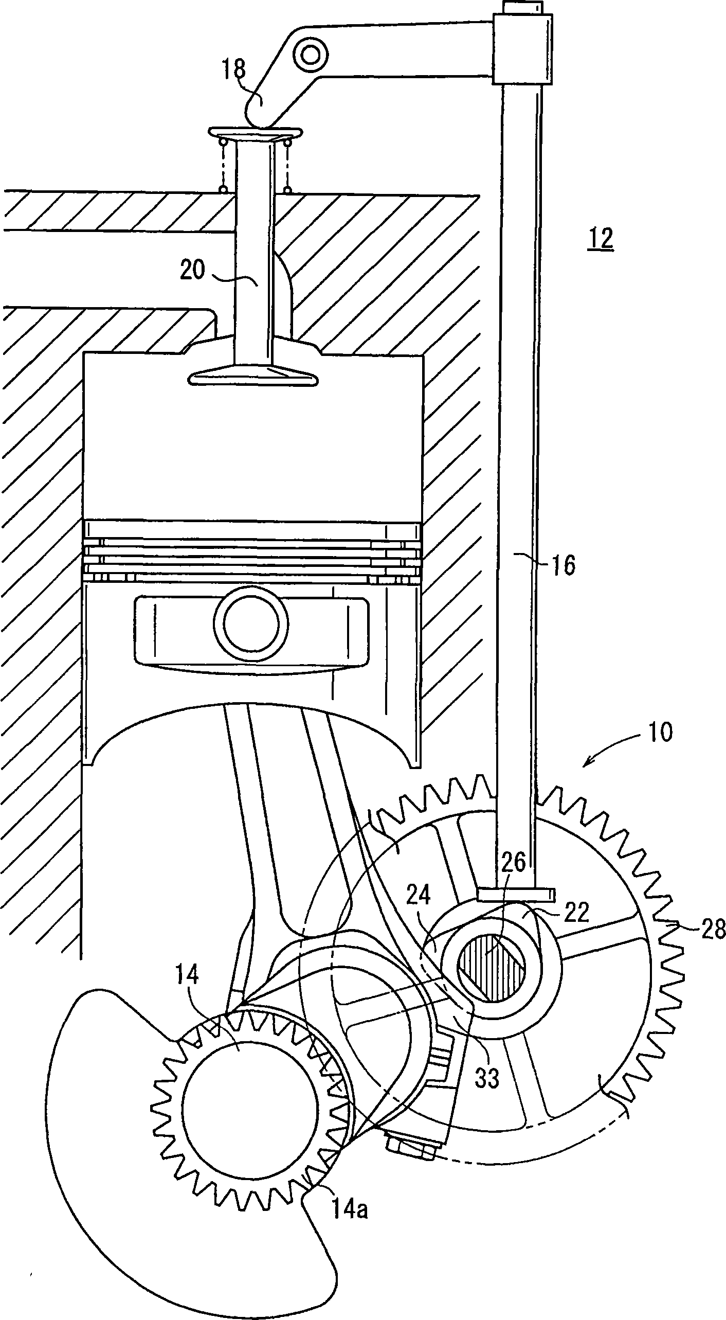
[0074] figure 1 An engine 12 incorporating an assembled camshaft 10 manufactured by a method of manufacturing a cam for a camshaft according to an embodiment of the present invention is schematically shown. The camshaft 10 is used in an engine 12, which may be a single-cylinder engine, for example. The camshaft 10 pushes the push rod 16 (one shown) upward in synchronization with the rotation of the crankshaft 14 to operate the rocker arm 18 (one shown) to open and close the valve 20.

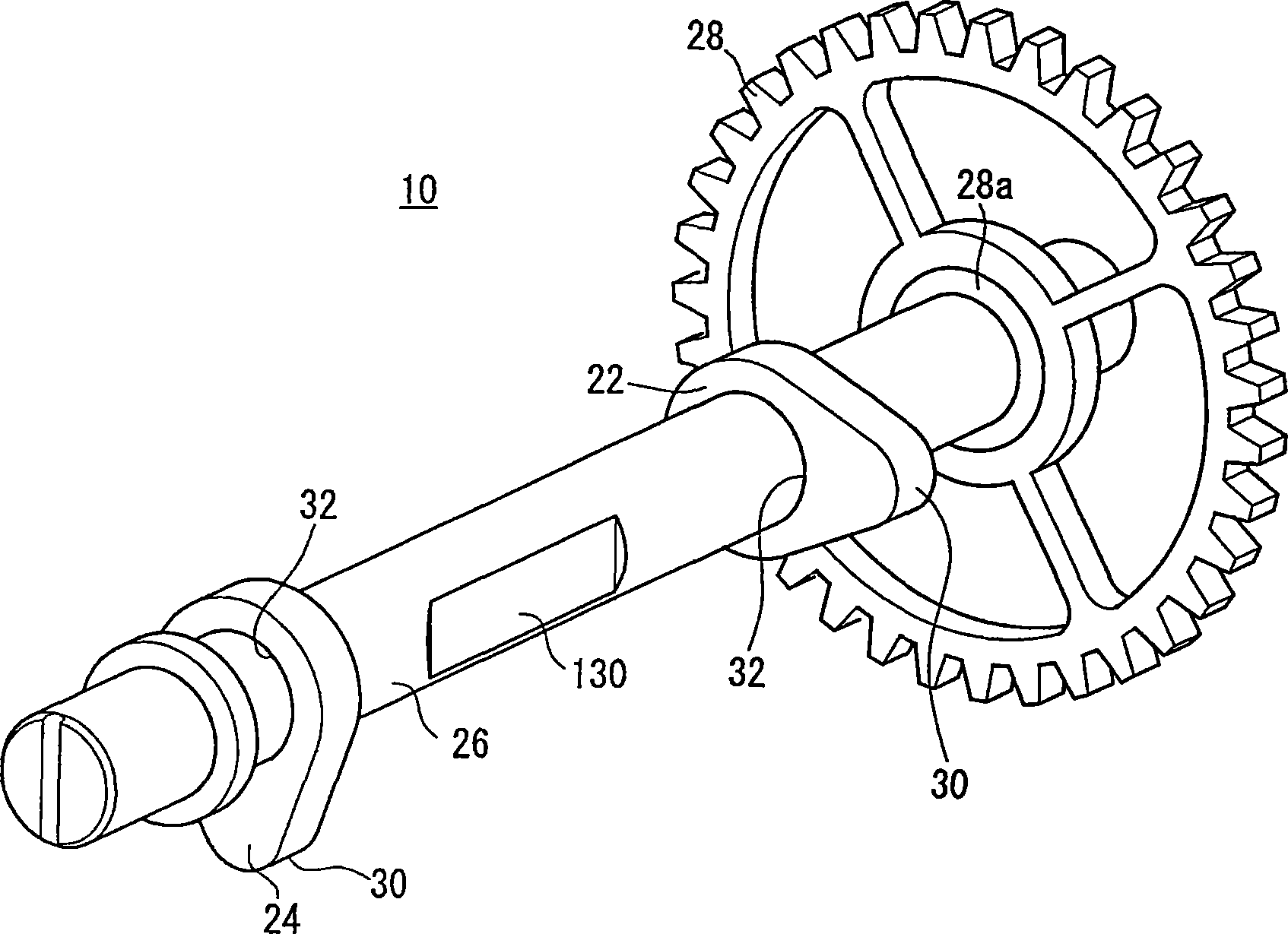
[0075] The valve 20 includes two valves, namely an intake valve and an exhaust valve, which are connected to the corresponding rocker arm 18 and the corresponding push rod 16. The camshaft 10 has two cams 22, 24 which are kept out of phase with each oth...


PUM


Abstract

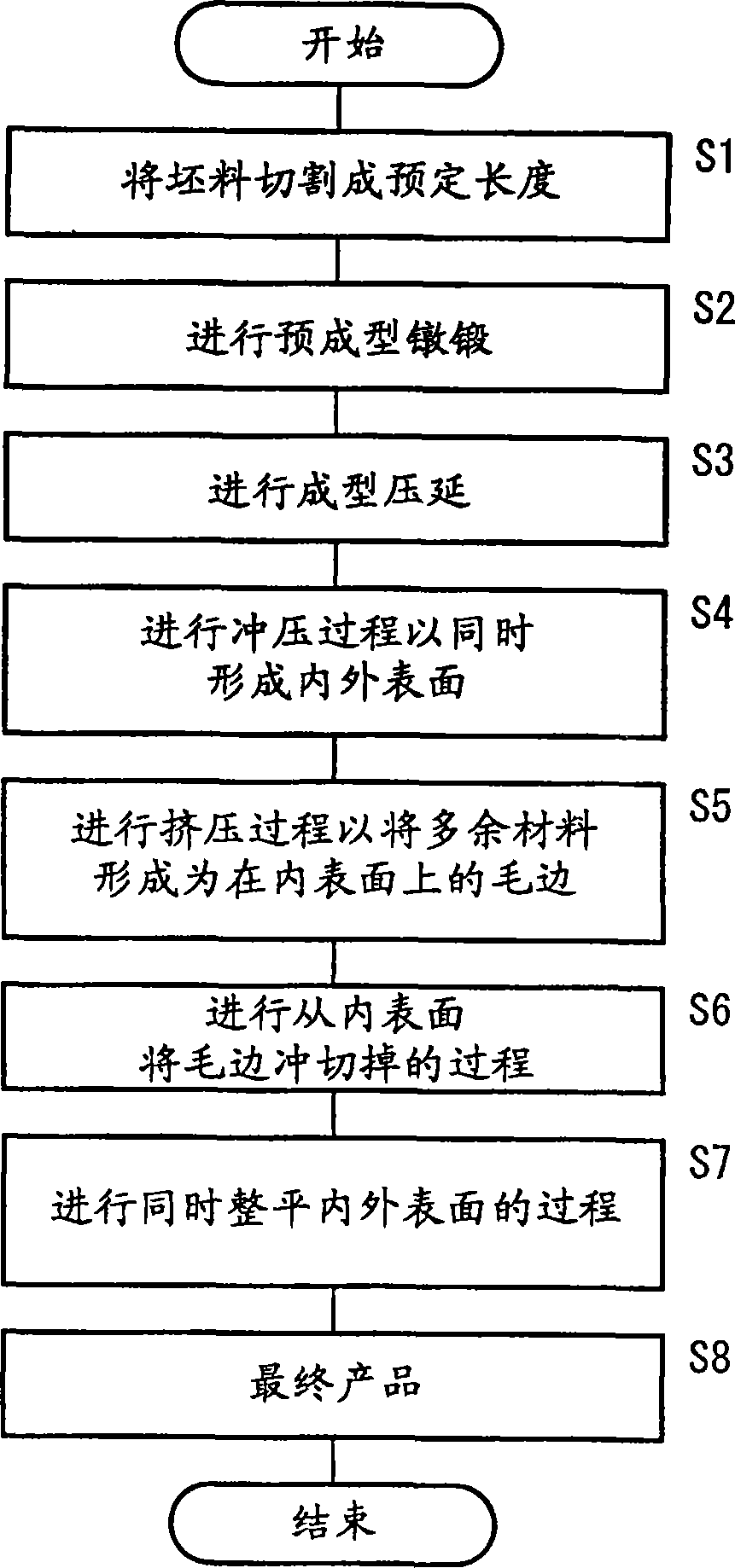
A method of manufacturing a cam for a camshaft, comprising the steps of continuously applying, to a billet having a volume larger by a specified volume than a final product, a plurality of cold forging steps formed of a preliminary outline upsetting, an outline drawing, a simultaneous piercing of inner and outer diameter surfaces, a press-molding forming excess amount as burrs on the inner diameter surface, a piercing of the inner diameter surface for removing the burrs from the inner diameter surface, and a simultaneous ironing of the inner and outer diameter surfaces. The final finishing (machining) of a cam (profile) surface can be eliminated, and the final product of the cam for the camshaft having a high dimensional accuracy can be provided.

Description

Technical field [0001] The present invention relates to a camshaft for opening and closing an engine valve, a method for manufacturing a cam for a camshaft, and a method for manufacturing a shaft for a camshaft. Background technique [0002] An assembled camshaft is known, which can rotate in a coaxial relationship with a crankshaft of a gasoline engine or the like, so as to control the timing of opening and closing the intake valve and exhaust valve of the gasoline engine. [0003] The assembled camshaft has a shaft in the form of a metal tube, and the shaft in the form of a metal tube is fixedly installed in a shaft insertion hole formed in the cam member by means such as press fitting. [0004] A conventional method for manufacturing the above-mentioned type of camshaft is disclosed in Japanese Laid-Open Patent Publication No. 8-90139. According to the disclosed method, the slender steel round rod whose volume corresponds to the cam to be produced is heated to 1250-1280°C, and...

Claims


Application Information

Patent Timeline
IPC IPC(8): F01L1/04
Inventor 竹岛史生佐竹浩二仓泽秀男大野幸三
Owner HONDA MOTOR CO LTD
Learn More