Controlling circuit of inleakage protector with life-stop indicator and releaser

A leakage protector and end-of-life technology, used in emergency protection circuit devices, automatic disconnection emergency protection devices, circuit devices, etc. The effect of reliable tripping

Inactive Publication Date: 2007-01-17
陈景正
View PDF0 Cites 4 Cited by
  • Summary
  • Abstract
  • Description
  • Claims
  • Application Information

AI Technical Summary

Problems solved by technology

[0002] The existing household leakage protection circuit breakers on the market will only trip when the leakage occurs, and the leakage protector as a product itself is helpless when it fails. Once this happens, the leakage protector itself is damaged, then Even if a leakage occurs, the leakage protector cannot be tripped normally, resulting in undue personal injury or property loss

Method used


Image

  • Controlling circuit of inleakage protector with life-stop indicator and releaser

Examples


Embodiment Construction

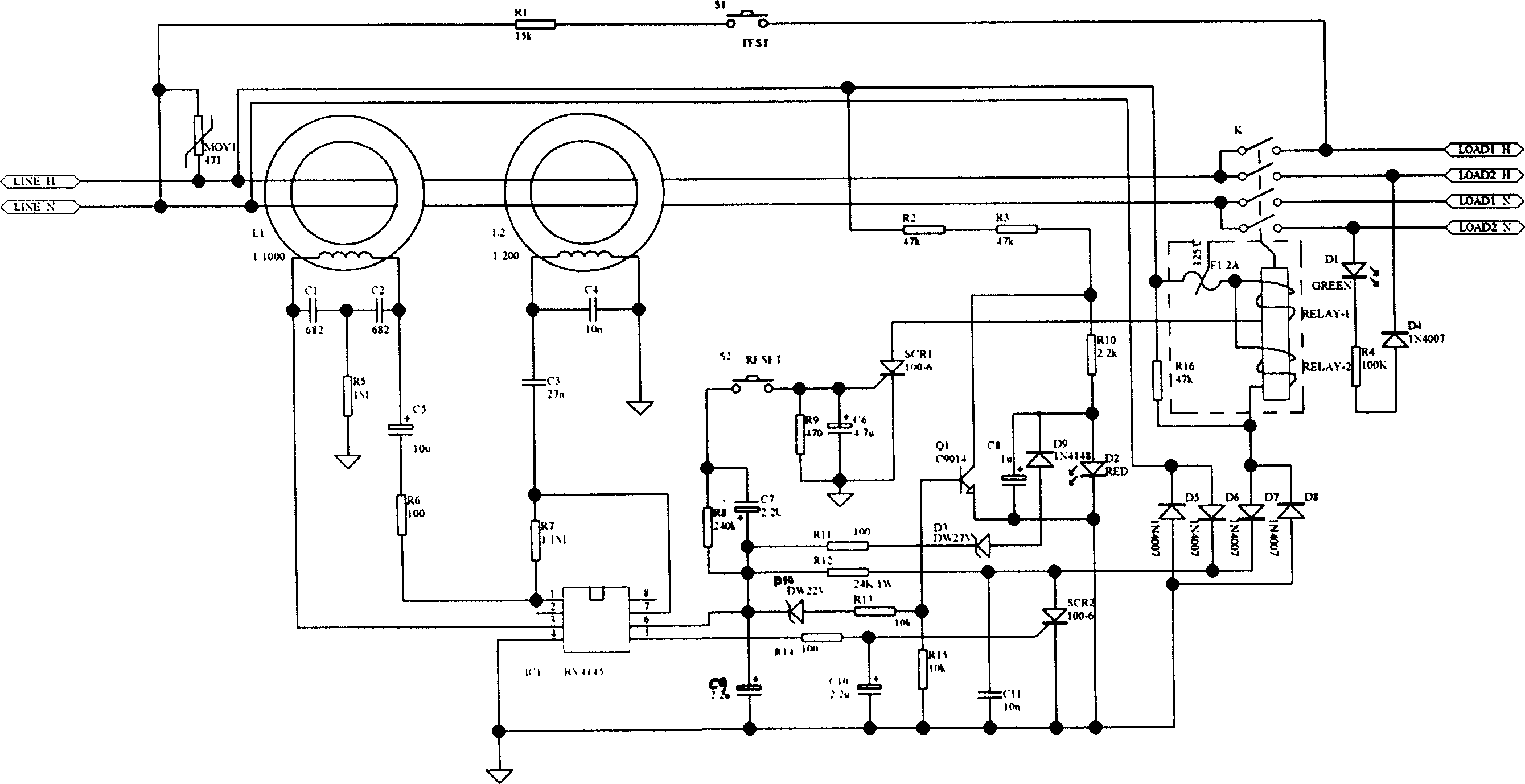
[0010] As shown in the figure, the main input lines 1H and 2N of the present invention pass through the inductor L1, and the capacitor C1 and capacitor C2 are connected in parallel with the inductor L1 after being connected in series. One end is connected in series with capacitor C5 and resistor R6 to pin 1 of microcontroller IC1, which can be RV4145 or 54123, and the other end of inductor L1 is connected to pin 3 of microcontroller IC1 for leakage detection. Pin 5 of microcontroller IC1 is connected to resistor R14. And drive the thyristor SCR2 after being grounded by C10, the thyristor SCR2 is connected in series with diodes D5, D6, D7, D8 and the tripping relay RELAY-2; the power supply pin 6 of the single-chip microcomputer IC1 is connected to the resistor R11 and the negative pole of the voltage regulator D3, and the voltage regulator tube The positive pole of D3 is connected in series with the positive pole of diode D9, and the negative pole of diode D9 is connected to th...


PUM


Abstract

A creepage protector controlling circuit with the end-of-life indication or trip, the characteristic is: adds the abnormity monitor circuit that can monitor the self-fault of the creepage protector automatically, indicates the fault automatically or trip directly when the key parts appears abnormity, in order to prevent electro-security accident and the person security when the creepage protector abates.

Description

Technical field [0001] The invention relates to a leakage protector control circuit with end-of-life indication or tripping. Background technique [0002] The existing household leakage protection circuit breakers on the market will only trip when the leakage occurs, and the leakage protector as a product itself is helpless when it fails. Once this happens, the leakage protector itself is damaged, then Even if a leakage occurs, the leakage protector cannot be tripped normally, resulting in undue personal injury or property loss. Contents of the invention [0003] In order to overcome the above-mentioned problems in the prior art, the object of the present invention is to provide a control circuit of a leakage protector that can indicate in advance or trip directly when the leakage protector itself is abnormal. [0004] The technical scheme adopted by the present invention to solve the technical problem is: the main input lines 1H, 2N pass through the inductor L1, the capa...

Claims


Application Information

Patent Timeline
Patent Type & Authority Applications(China)
IPC IPC(8): H02H3/14H02H3/04
Inventor 陈景正
Owner 陈景正
Why Eureka
Try Eureka