Heat exchanger

A heat exchanger and heat exchanger technology, applied in heat exchange equipment, heat exchangers, heat exchanger types, etc., can solve problems such as process and material limitations, increase in cooling liquid, and increase in specific power of heat exchangers

Active Publication Date: 2007-01-17
BEHR GMBH & CO KG
View PDF0 Cites 10 Cited by
  • Summary
  • Abstract
  • Description
  • Claims
  • Application Information

AI Technical Summary

Problems solved by technology

[0004] As the specific power of the heat exchanger increases, so does the risk of the coolant boiling, which significantly reduces power and service life
[0005] Finally, due to the presence of st

Method used


Image

  • Heat exchanger
  • Heat exchanger
  • Heat exchanger

Examples


Embodiment Construction

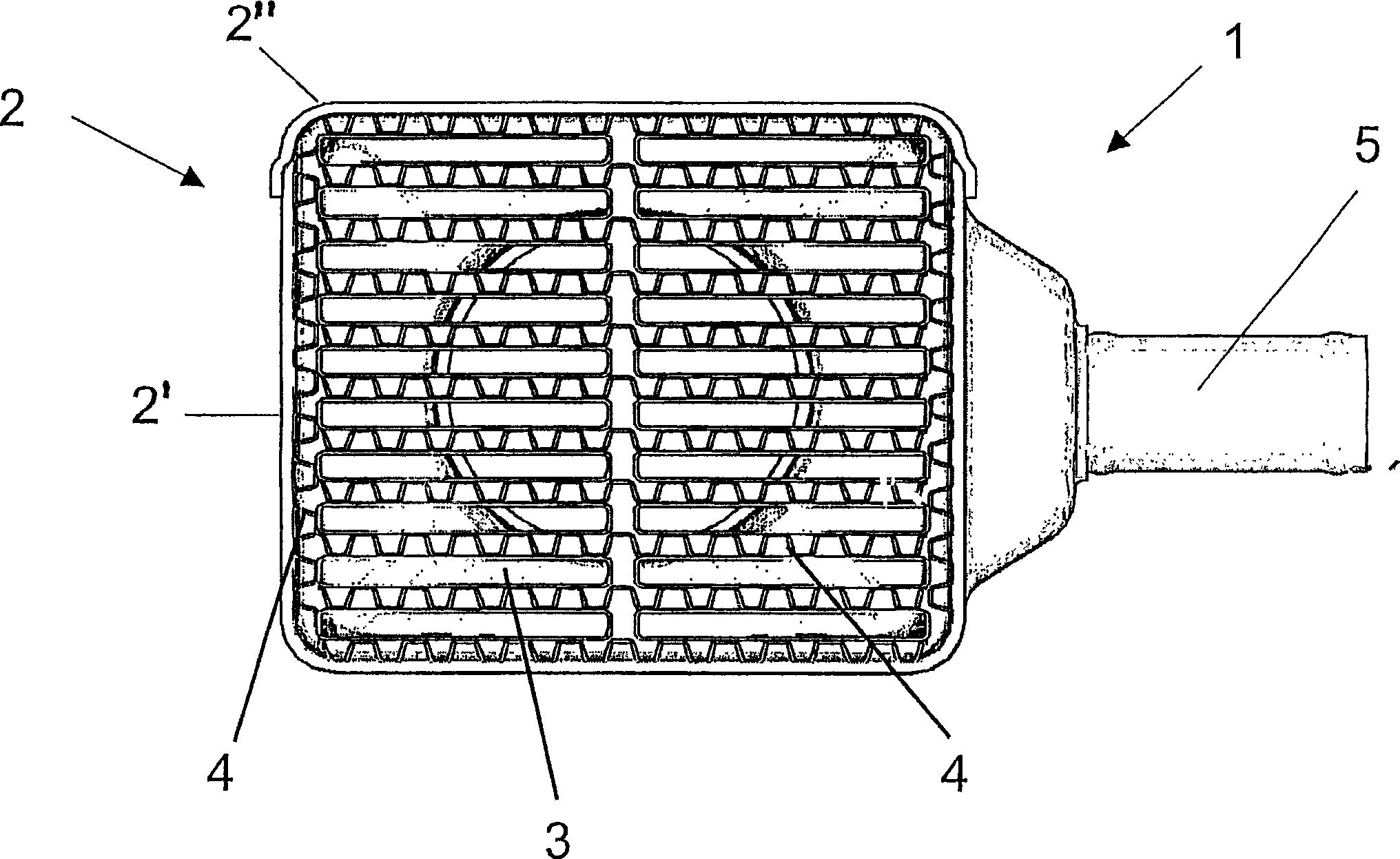
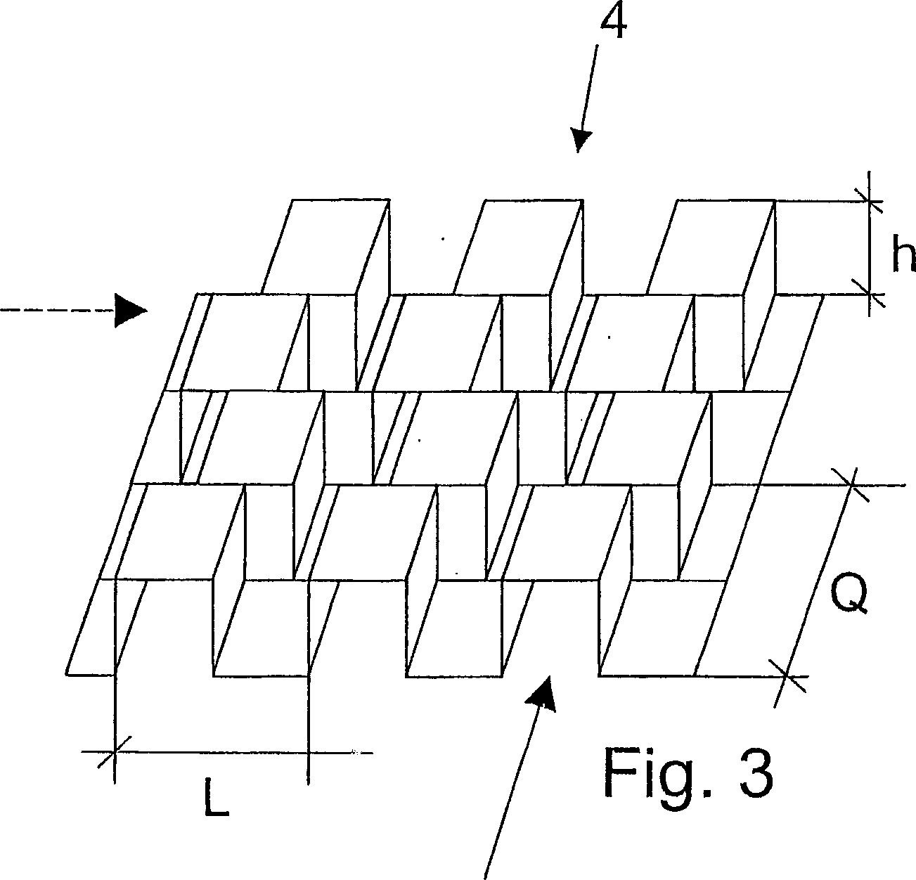
[0021] The exhaust gas heat exchanger 1 has a two-part housing 2 and a plurality of tubes 3 arranged in the housing 2 . Between the tubes 3 and between the housing 2 and the tubes 3 there are finned plates 4 as structural elements, where the finned plates 4 have a saw-toothed structure according to the above-described embodiment, as shown in FIG. 3 , and will This will be described in detail later. Here, the tube 3 is a flat tube.

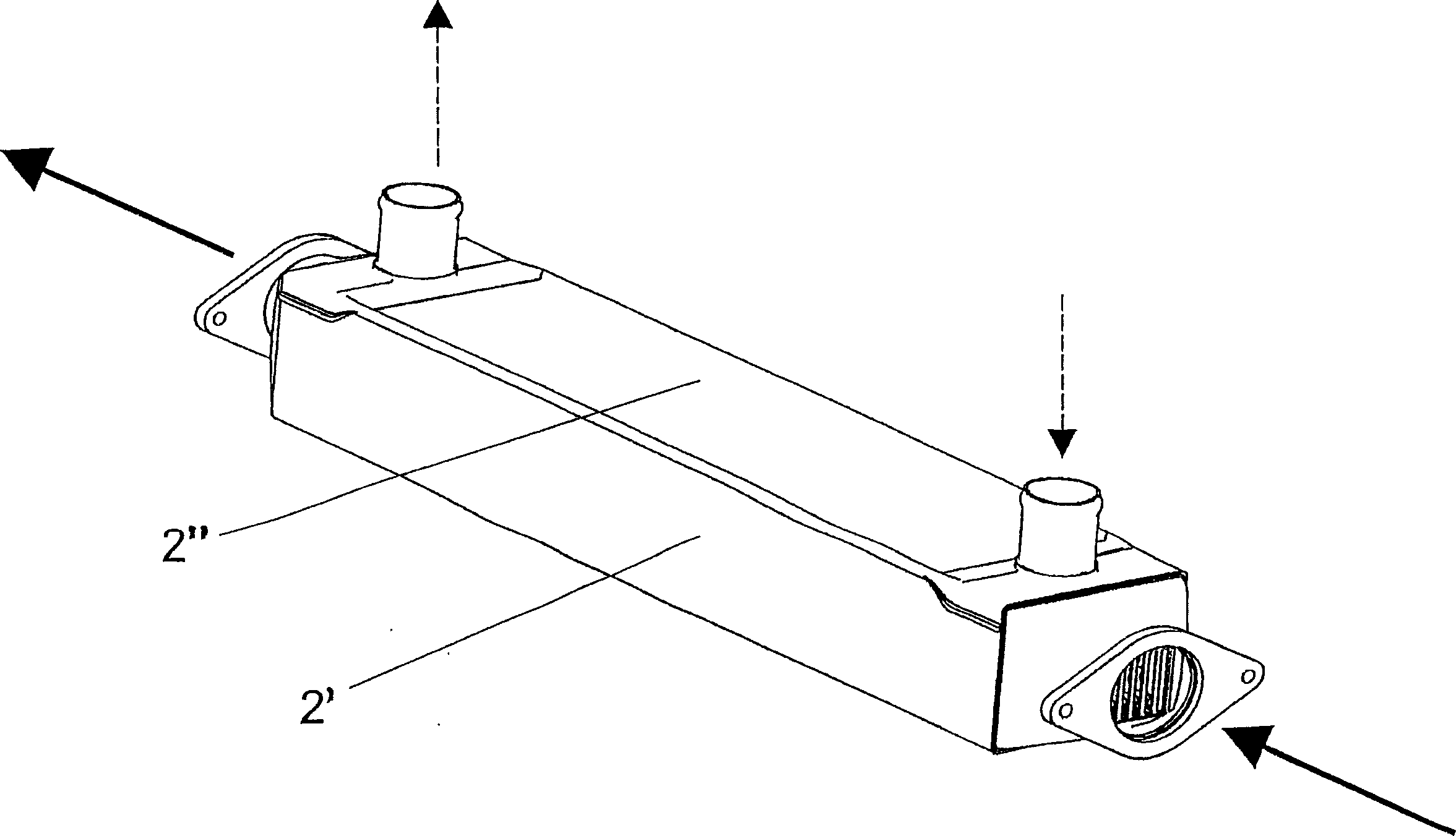
[0022] Exhaust gas from the engine to be cooled (gaseous first medium) flows in the pipe 3 , and in FIG. 2 the direction of flow is indicated by two arrows drawn in solid lines. The tube 3 is arranged in the housing 2 and consists of a U-shaped first housing part 2' and a housing cover 2", wherein the cover is placed on the first housing part 2' from top to bottom .In order to allow the coolant (liquid second medium) to flow in and out, two coolant connections 5 are provided in the housing cover 2 ", while in Fig. 2 the flow direction of the cool...


PUM


Abstract

The invention relates to a heat exchanger (1), especially for motor vehicles, comprising a housing (2) and at least one pipe (3) disposed inside said housing (2). The heat exchanger is characterized in that structures (4) are provided in the area between the pipes (3) and the housing (2) and/or between the pipes (3).

Description

technical field [0001] The invention relates to a heat exchanger for automobiles. Background technique [0002] Today's engines are increasingly required to reduce emissions and fuel consumption. To meet these demands, measures such as increased boosting and more precise influence of combustion conditions are required. For automotive heat exchangers, this creates higher operating conditions, such as increased gas and coolant pressure, temperature and flow. At the same time, the requirements for specific power (Leistungsdichten) and service life are increasing. Therefore, it is necessary to adopt a new cooling concept locally. Thus, in the charge air cooler, the traditionally used air / air cooler is at least partly replaced by an air / liquid cooler in order to achieve the power and specific power required by the high supercharging of the engine. In exhaust gas heat exchangers, the exhaust gas recirculation rate is constantly increasing under increasing operating conditions s...

Claims


Application Information

Patent Timeline
IPC IPC(8): F28D7/16F28F1/04F28F1/12F28F1/14F28F27/02
CPCF28F1/14F28D21/0003F28F9/0268F28D7/1653F28F1/126F28F9/026F28F2215/04
Inventor 彼得·格斯克斯丹尼尔·亨德里克斯赖纳·卢茨乌尔里希·毛赫尔延斯·里希特马丁·申德勒米夏埃尔·施密特
Owner BEHR GMBH & CO KG
Why Eureka
Try Eureka