Plunger type master cylinder

一种柱塞型、主缸的技术,应用在液压制动传动装置、流体压力致动装置、遥控马达等方向,能够解决插入、活塞跑到杯外、歪斜等问题

Inactive Publication Date: 2007-01-24
ADVICS CO LTD
View PDF1 Cites 7 Cited by
  • Summary
  • Abstract
  • Description
  • Claims
  • Application Information

AI Technical Summary

Problems solved by technology

[0006] However, the arrangement disclosed in this publication has the problem that the throttle valve parts are structurally complex and thus the yield is low
But the secondary piston (the one in front) may move back too far and go out of the cup
If this happens, the secondary piston may damage the cup or the secondary piston may be inserted into the cup in an unnatural manner or askew when the secondary piston is then returned to its non-operating position

Method used


Image

  • Plunger type master cylinder
  • Plunger type master cylinder
  • Plunger type master cylinder

Examples


Embodiment Construction

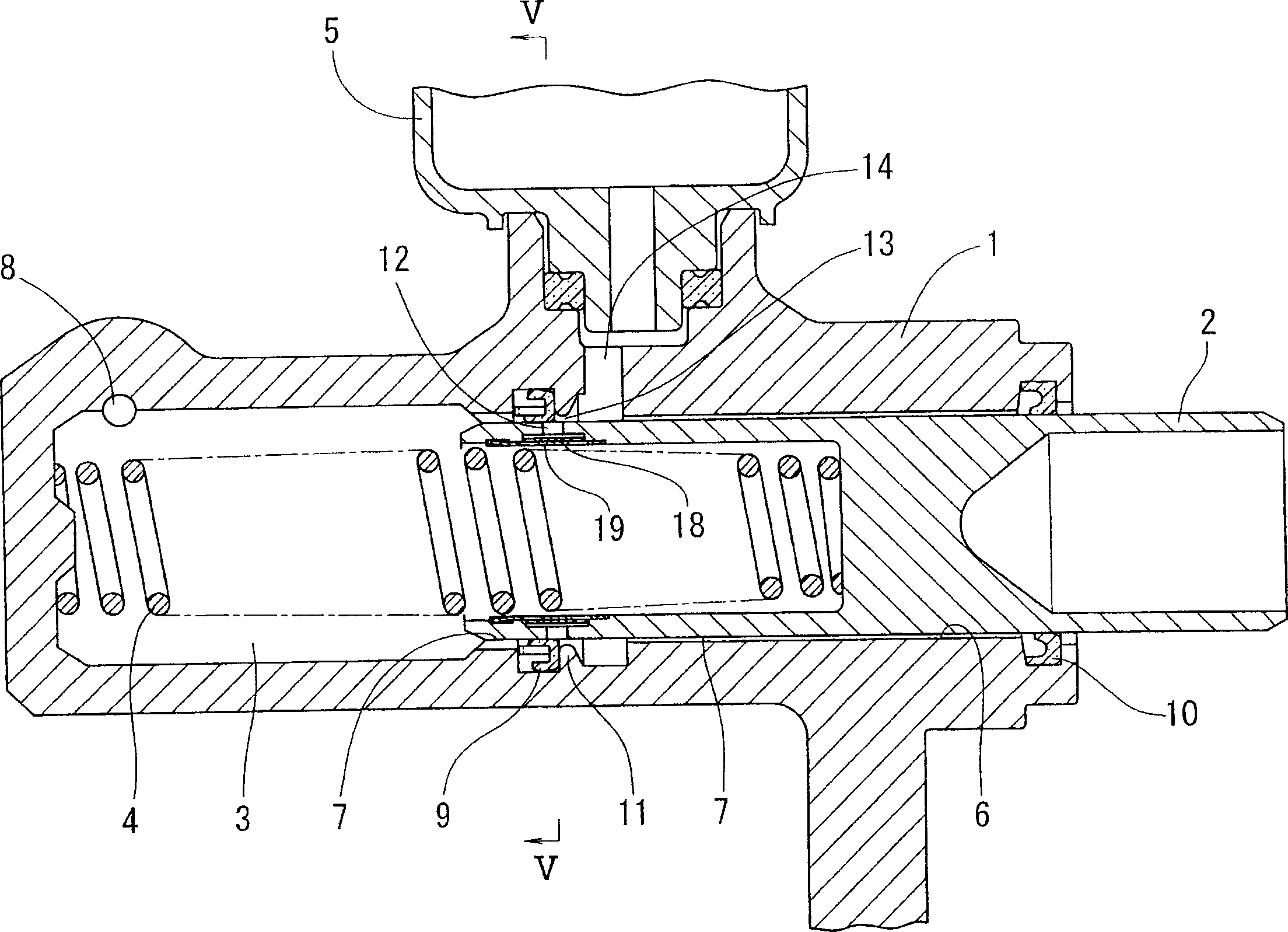
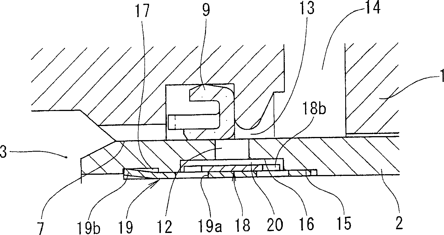
[0027] will now refer to Figure 1 to Figure 8 A master cylinder embodying the invention is described. figure 1 The basic structure of the master cylinder according to the invention is shown. The master cylinder includes a cylinder body 1 , a piston 2 installed in the cylinder body 1 , a return spring 4 for the piston 2 and a storage tank 5 . A pressure chamber 3 is defined in the cylinder body 1 in which a brake fluid pressure is generated by pressurizing a hydraulic fluid therein with a piston 2 . The pressure chamber 3 comprises an outlet orifice 8 through which the hydraulic pressure generated therein is discharged.

[0028] The primary cup 9 and the secondary cup 10 are housed in grooves formed in the inner circumference of the cylinder 1 and held in place by the cylinder 1 . The main cup 9 seals the outer circumference of the piston 2 . The secondary cup 10 is pressed against the outer periphery of the piston 2, thereby sealing the interior of the cylinder 1 from the...


PUM


Abstract

A master cylinder includes a piston received in a cylinder body and formed with piston ports. An annular groove is formed in the inner periphery of the piston in its area where the piston ports are formed. An arcuate plate is received in the annular groove. A sleeve is inserted into the arcuate groove to retain the arcuate plate in the annular groove. A gap as a fluid passage is defined between the arcuate plate and the inner surface of the annular groove. A pressure chamber defined in the cylinder body communicates with a communication passage communicating with a reservoir through the above gap, cutouts of holes formed in the arcuate plate and holes formed in the sleeve. When hydraulic fluid flows rapidly from the pressure chamber toward the reservoir, the arcuate plate is adapted to elastically and radially expand, thus closing some of the piston ports.

Description

technical field [0001] The present invention relates to a plunger-type master cylinder used in a vehicle braking system, and more particularly to a cylinder that smoothly draws hydraulic fluid from a reservoir during automatic braking control and limits hydraulic fluid from pressure during manual braking. Simple and reliable master cylinder with return flow from chamber to tank. Background technique [0002] Many vehicle hydraulic braking systems today are equipped with automatic braking functions such as Traction Control (TRC) or Electronic Stability Control (ESC). [0003] In some such braking systems, during automatic braking, hydraulic fluid is supplied from a reservoir to the desired unit through a pressure chamber in the master cylinder. In such a braking system, therefore, a smooth pumping of hydraulic fluid into the pressure chamber of the master cylinder is required. Also, when the brake pedal is depressed, it is necessary to limit the return flow of hydraulic flu...

Claims


Application Information

Patent Timeline
Patent Type & Authority Applications(China)
IPC IPC(8): B60T11/16
CPCF15B7/08F15B7/10B60T11/16
Inventor 坪内薰
Owner ADVICS CO LTD
Why Eureka
Try Eureka