
Fume exhaust fan of fume focusing cover with air inlet concave chamber

The technology of a range hood and a fume collecting hood is applied in the field of range hoods, which can solve the problems of poor range hood, unsightly appearance, complicated structure, etc., and achieves high range hood efficiency, good range hood effect and good operating environment. Effect

Inactive Publication Date: 2007-01-24
HUNAN XUNDA JI TUAN YOU XIAN GONG SI
View PDF3 Cites 4 Cited by
  • Summary
  • Abstract
  • Description
  • Claims
  • Application Information

AI Technical Summary

Problems solved by technology

During the process of oil fume floating upward, a small amount of oil fume floats outside the fume collecting hood, resulting in more and more oil fume in the kitchen space, which has a negative impact on the operating environment
The "range hood" disclosed in Chinese patent application number 01276895.2, in addition to two large air inlets, has some air inlets on the vertical peripheral wall of the hood, but because the oil smoke gas flowing outwards will escape from the range hood When the fume collecting hood spreads rapidly to the surroundings, the oil fume suction effect of the side oil suction hole is not good enough
Chinese Patent Application No. 95244534.4 discloses the "double suction type range hood", two main suction large circular air intake holes on the smoke collecting hood panel, and several small air intake holes are opened on the periphery of the panel. This small air intake hole Also for the oil fume that diffuses to the outside of the range hood, the secondary inhalation rate is even worse, and they cannot prevent the adverse consequences of oil fume polluting the environment
Chinese Patent Application No. 95224919.7 discloses "deep range hood with smoke collection chamber". This structure increases the height of the range hood. In order to increase the cross-sectional area of ​​the smoke collection chamber, the bent plate of the smoke collection hood needs to be longer, thereby increasing the volume of the range hood overall. The feeling of the head, and it is not beautiful, and the oily fumes are diffused outwards, which cannot be sucked away
And the structure is very complicated, the appearance is not beautiful, and the effect of absorbing oil fume is poor

Method used


Image

  • Fume exhaust fan of fume focusing cover with air inlet concave chamber
  • Fume exhaust fan of fume focusing cover with air inlet concave chamber
  • Fume exhaust fan of fume focusing cover with air inlet concave chamber

Examples


Embodiment 1

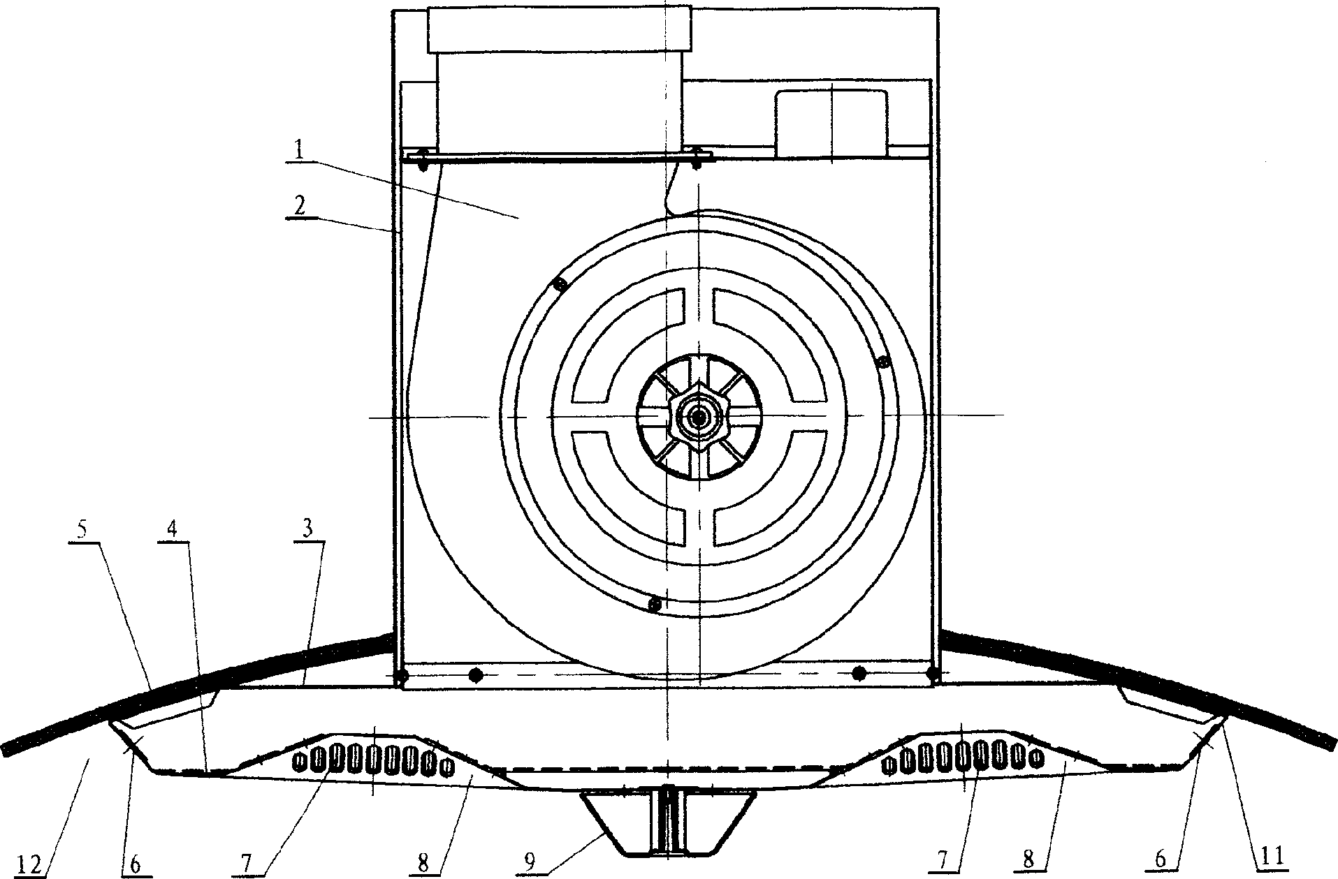
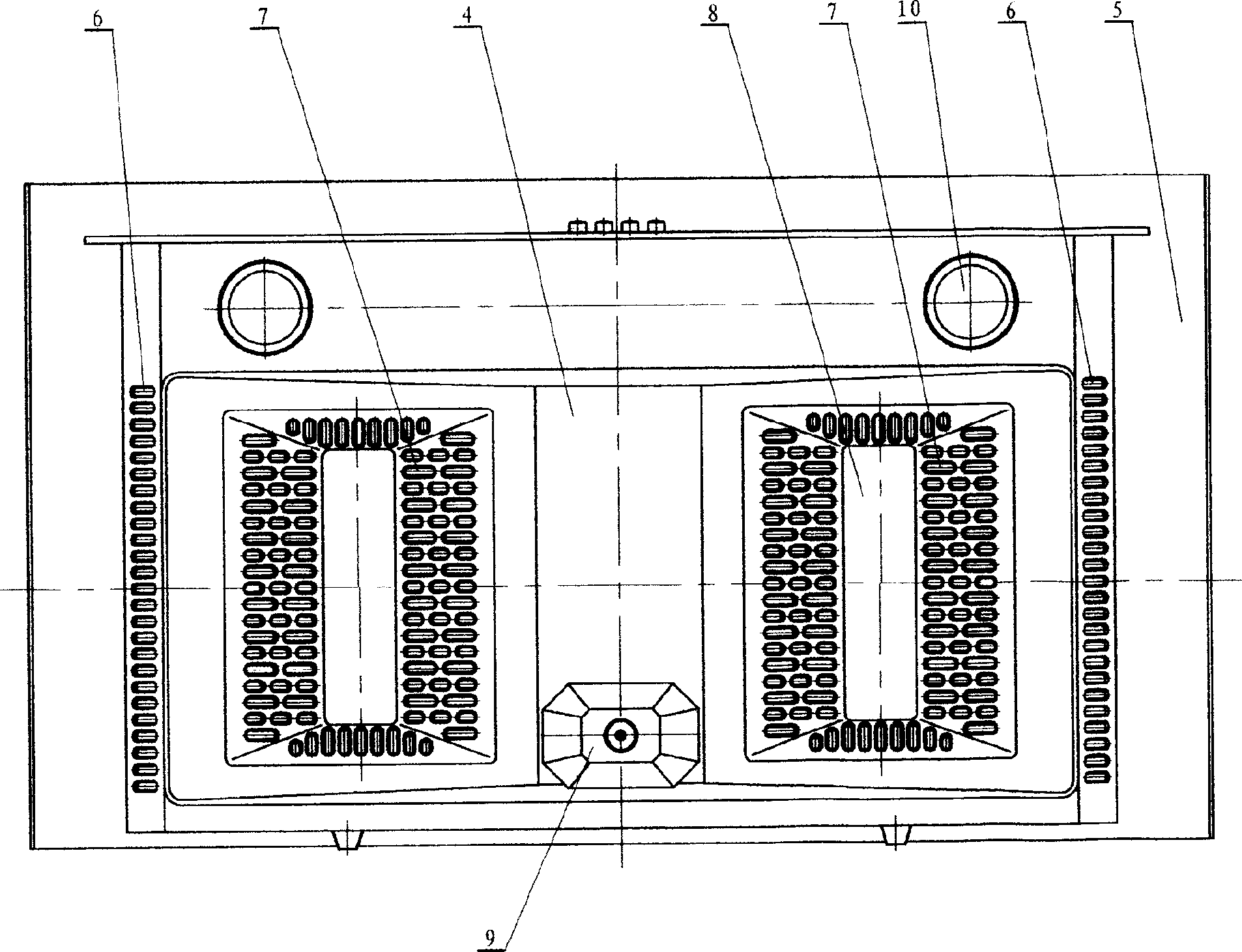
[0015] Example 1, see figure 1 and figure 2 . This is a smoke collecting hood 4 with two main air inlet cavity 8 in the shape of a prism, and a plurality of main air inlets 7 are evenly distributed on the four oblique sides of the quadrangular truss, and the shape of the main air inlet 7 is Long hole. The upper curved side plates 11 at both ends of the smoke collecting hood 4 are sandwiched with the downwardly extending part of the outer smoke collecting hood 5 to form left and right secondary air inlet concave cavities 12, which are opened on the upward curved side plates 11. There are a plurality of elongated secondary air inlets 6. The main air inlet 7 and the auxiliary air inlet 6 are processed at the same time when the smoke collecting hood 4 is being processed, and the air outlet is punched out of the steel plate by stamping to form a flanging hole, that is, the three sides of the hole are torn apart from the steel plate, and the other side is connected to the steel ...

Embodiment 2

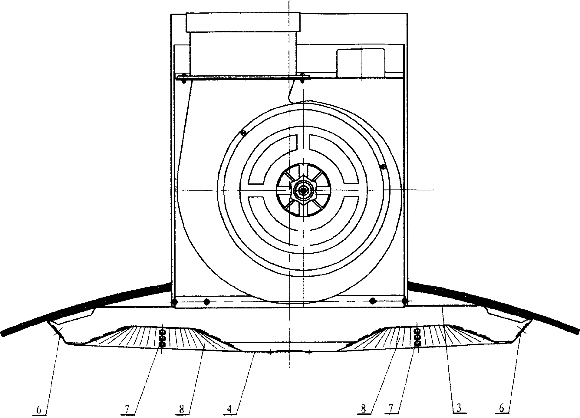
[0016] Example 2, see image 3 and Figure 4 . This is the shape of the two main air inlet cavities 8 of the fume collecting hood 4 in the shape of a truncated cone (or a sphere). The shape of the tuyere is a long strip hole. The upper curved side plates 11 at both ends of the smoke collecting hood 4 are sandwiched with the downwardly extending part of the outer smoke collecting hood 5 to form left and right secondary air inlet concave cavities 12, which are opened on the upward curved side plates 11. There are long side air inlets. The main air inlet 7 and the auxiliary air inlet 6 are processed simultaneously when processing the smoke collecting hood 4, and the tuyere is processed into a flanged hole.

Embodiment 3

[0017] Example 3, see Figure 5 and Image 6 . The main air inlet cavity 8 on the fume collecting hood 4 is a circular frustum, and the main air inlet 7 is formed on the side wall of the circular table and the upper bottom of the circular table. The tuyere shape of a plurality of main air inlets 7 on the side wall is a long hole, and the main air inlets 7 on the upper bottom are round holes. In this example, when the tuyere is being processed, all the steel plates at the tuyere are punched open to form holes.


PUM


Abstract

Blower fan is installed inside chassis. Inner shell body of fume-collecting hood is installed at low end of chassis. External fume-collecting hood is joined and fixed on inner shell body. There are concave cavities of main air inlet on board of the fume-collecting hood. Multiple main air inlets are made on perisporium of concave cavity. Multiple secondary air inlets are prepared on side plates up bent from two ends of fume-collecting hood. Concave type cavities of secondary air inlets are formed between extended part of external fume-collecting hood and side plates up bent from two ends of fume-collecting hood. When apparatus of sucking oil fume is in use, concave cavities of main air inlets, and concave cavities of secondary air inlets form zone of negative pressure of sucking oil fume. Advantages are: simple structure, goodly outline, and good effect of sucking oil fume. The disclosed cover is suitable to apparatus of sucking oil fume for common people.

Description

technical field [0001] The invention relates to a technique for removing cooking smoke, in particular to a range hood with a smoke collecting hood having an air inlet cavity. Background technique [0002] Currently used range hoods are provided with a corresponding number of range hoods according to the number of burners in the user's stove. The oil suction hole of the commonly used range hood is a large-diameter circular air intake hole, while the smoke collecting hood plate is a flat plate, and the air intake hole is a flat hole on the flat plate. During the process of oil fume floating upward, a small amount of oil fume floats out of the fume collecting hood, resulting in more and more oil fume in the kitchen space, which has a negative impact on the operating environment. The "range hood" disclosed in Chinese patent application number 01276895.2, in addition to two large air inlets, has some air inlets on the vertical peripheral wall of the hood, but because the oil smo...

Claims


Application Information

Patent Timeline
Patent Type & Authority Applications(China)
IPC IPC(8): F24C15/20
Inventor 彭卫伍斌强刘坤明伍奕
Owner HUNAN XUNDA JI TUAN YOU XIAN GONG SI
Learn More