
Method and its machine for repairing display panel bright spot

A display panel and machine technology, applied in instruments, nonlinear optics, optics, etc., can solve problems such as complex structure, large space, and time-consuming

Inactive Publication Date: 2007-01-24
AU OPTRONICS CORP
View PDF0 Cites 3 Cited by
  • Summary
  • Abstract
  • Description
  • Claims
  • Application Information

AI Technical Summary

Problems solved by technology

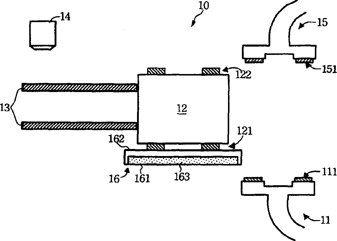
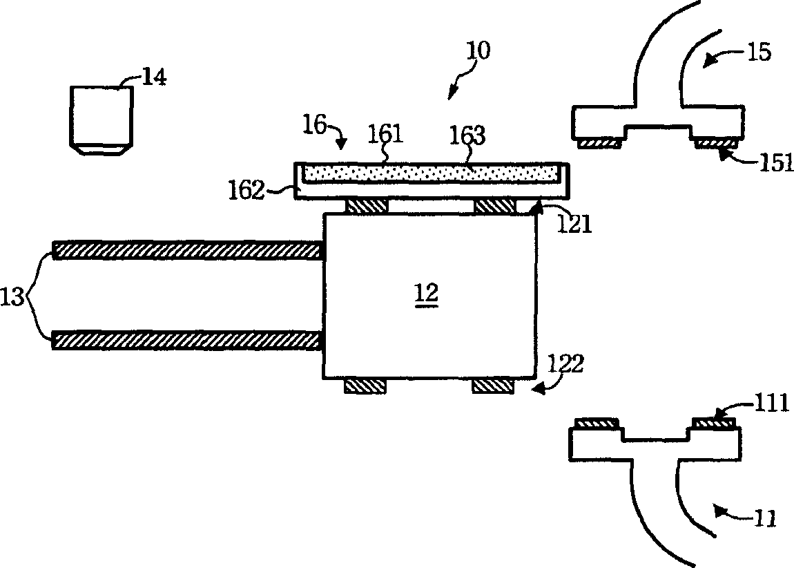
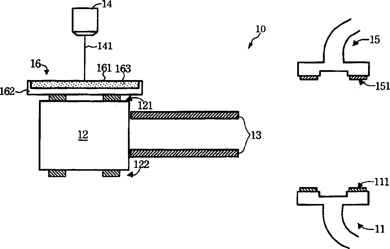
[0008] However, the following disadvantages are evident for the above-mentioned machine 10: 1) the working platform 12 must be "turned over" and the working platform 12 must be "moved" directly under the laser generating device 14, and furthermore, after the repair, the working The platform 12 must be "removed" to its original position. For this, the above-mentioned laser repair process will consume a lot of time. Generally speaking, the total time for the display panel 16 to be removed from the working platform 12 after being erected under the working platform 12 is as long as 17 seconds
2) The overturning mechanism of the machine 10 and the setting of the guide rail 13 will not only make the structure complex, but also cause unstable transmission due to the complex structure
3) The arrangement of the laser generating device 14 and the working platform 12 is too scattered, so that the whole machine 10 takes up a large space

Method used


Image

  • Method and its machine for repairing display panel bright spot
  • Method and its machine for repairing display panel bright spot
  • Method and its machine for repairing display panel bright spot

Examples


Embodiment Construction

[0042] Please refer to figure 2 , figure 2 is a schematic illustration of a machine 20 of the present invention. The machine 20 of the present invention is used to repair bright spots on a display panel 26 . The machine 20 comprises a first robotic arm 21 , a working platform 22 and a laser generating device 24 . The first automatic arm 21 moves the display panel 26 to the working platform 22 . Wherein, the first automatic arm 21 has two first vacuum chucks 211 , which are adsorbed on the lower surface 261 of the display panel 30 by the first vacuum chucks 211 , so that the first automatic arm 21 can transport the display panel 26 .

[0043] Moreover, the working platform 22 is used for erecting the display panel 26 thereon. Wherein, the working platform 22 may have two adsorption components 221 , and the adsorption components 221 are disposed below the working platform 22 . The display panel 26 from the first automatic arm 21 can be adsorbed on the upper surface 262 of...


PUM


Abstract

The machine includes working platform and laser creation device. The working platform possesses at least one adsorbing mechanism. Being setup below the working platform, the adsorbing mechanism is in use for adsorbing up surface of display faceplate. Being setup below the working platform, laser creation device can generate laser to display faceplate in order to repair bright spot on display faceplate.

Description

technical field [0001] The invention relates to a method and its machine for repairing a display panel, in particular to a method and its machine for repairing a bright spot of a display panel. Background technique [0002] Currently, in the liquid crystal display panel (LCD), the repair method for darkening the bright spots is to put the voltage of the bright spots in a high voltage state, so that light cannot penetrate, thereby achieving the effect of shading. In order to make the position of the above-mentioned bright spot in a high voltage state, the pixel electrode substrate in the display panel can generally be irradiated with laser light, so that the relative position of the above-mentioned bright spot is in a high voltage state due to a short circuit. Repairs the effect of dark spots. [0003] The machines used to repair the bright spots of the above-mentioned display panels are further described below. Please refer to Figure 1A , Figure 1A is a schematic diagram...

Claims


Application Information

Patent Timeline
IPC IPC(8): G02F1/13
Inventor 刘象强陈培军苏胜彬
Owner AU OPTRONICS CORP
Learn More