Supercharge Your Innovation With Domain-Expert AI Agents!

Ion source control system

一种控制系统、离子源的技术,应用在离子束管、放电管、电气元件等方向,能够解决系统切断等问题

Inactive Publication Date: 2007-01-24
SAINTECH
View PDF1 Cites 2 Cited by
  • Summary
  • Abstract
  • Description
  • Claims
  • Application Information

AI Technical Summary

Problems solved by technology

However, these systems have tended to operate on power as is generally the case in the prior art, so have these systems shut down due to spurious events in the vacuum chamber, even if those spurious events are not truly catastrophic event

Method used


Image

  • Ion source control system
  • Ion source control system
  • Ion source control system

Examples


Embodiment Construction

[0025] The applicant's PCT / AU01 / 01548 describes a gridless ion source operating in pulsed mode. One of the embodiments of the present invention describes an ion source in which the anode voltage is pulsed to generate an intermittent ion current. A specific example describes that the period of the anode voltage is on the order of 1 second.

[0026] The present inventors have realized that while the ion source can repeatedly activate the ion current, the control system can operate the ion source to intermittently eliminate the ion current. The present inventors have further realized that if the ion current is eliminated at the timescale at which instabilities are generated or faster, the complex protection circuitry required to detect and eliminate instabilities can be reduced or eliminated altogether.

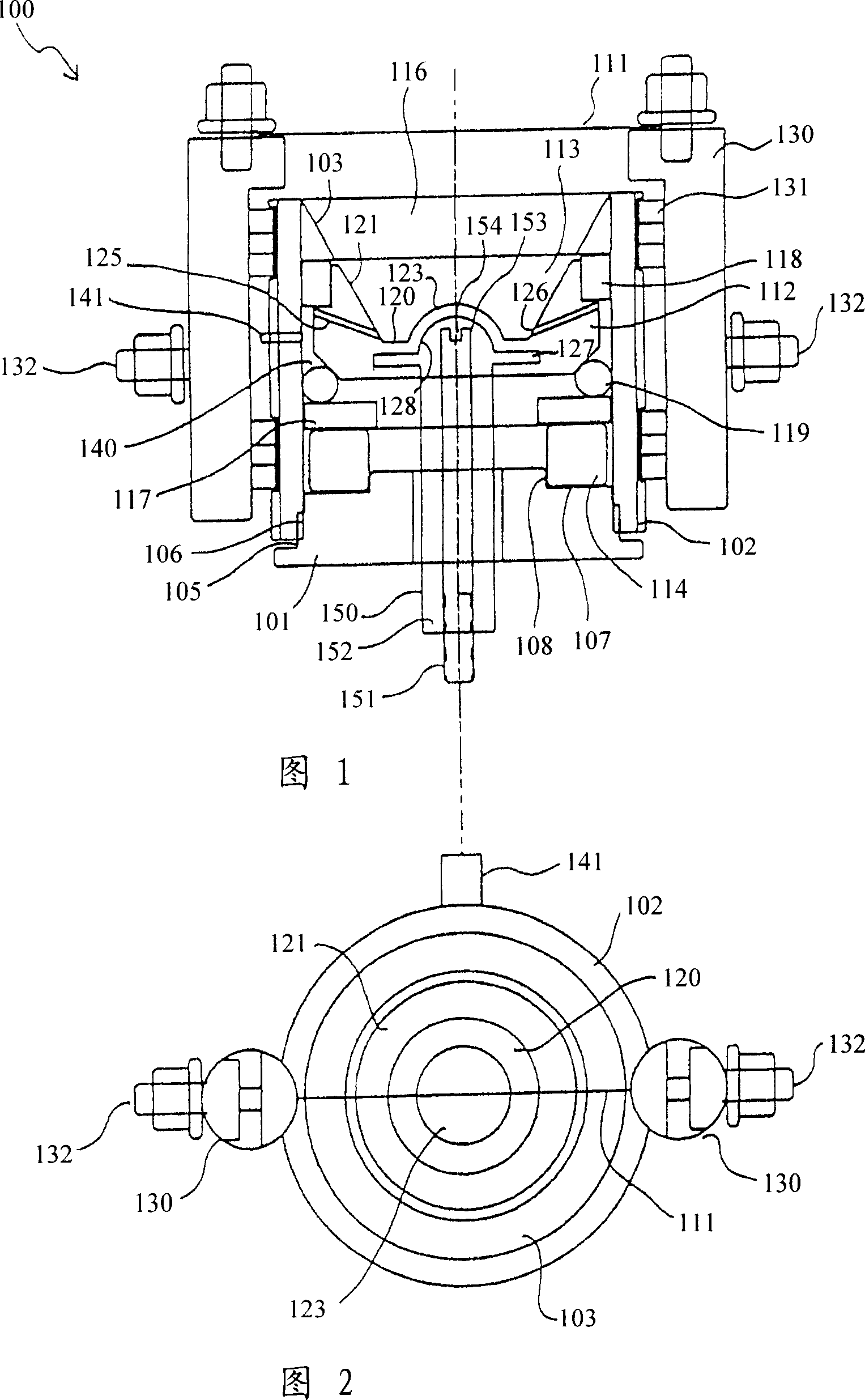
[0027] Referring to Figures 1 and 2, there is shown an ion source 100 in accordance with a preferred embodiment of the present invention. The ion source 100 includes a base pl...


PUM


Abstract

A gridless ion source operated from a control system (201) that generates an anode voltage (215) comprising a power rectified signal such that said anode voltage is between a first voltage greater than a threshold and a voltage less than said threshold modulated between the second voltage. The power rectified signal is provided by a transformer (210) receiving a power input (211). The output of the transformer (213) is rectified by a bridge rectifier (214). In a preferred embodiment, the threshold is an ionization threshold, so that the ion current is activated and deactivated in each cycle.

Description

technical field [0001] The present invention relates to a control system for an ion source, in particular to a control system for an open ended gridless ion source. Background technique [0002] In the field of thin film fabrication gridless ion sources are already known, eg from US 4862032, which provide a broad area ion beam capable of providing ion assistance for thin film deposition processes. [0003] Systems such as those described in US 4862032 require larger airflows in order to initiate and maintain the ionic current. Because of these large gas flows, the ion source is susceptible to transients that can occur in the vacuum chamber in which these systems operate. The control system therefore requires circuitry for dealing with possible instabilities. Any fluctuations in the vacuum chamber will cause a rapid drop in anode voltage or gas flow or both. It prevents momentary spikes from turning into catastrophic events, such as arcing in a vacuum chamber. If the tran...

Claims


Application Information

Patent Timeline
Patent Type & Authority Applications(China)
IPC IPC(8): H01J37/08H01J27/02
CPCH01J37/08H01J27/146
Inventor 塞蒂·G·韦恩沃勒·V·威廉
Owner SAINTECH
Features
  • R&D
  • Intellectual Property
  • Life Sciences
  • Materials
  • Tech Scout
  • Unparalleled Data Quality
  • Higher Quality Content
  • 60% Fewer Hallucinations
Learn More