Nozzle system for processing netted material

A technology of mesh material and nozzle, applied in heat treatment furnace, thin material treatment, heat treatment equipment, etc., can solve the problems of uneven heat treatment results and reduction of carrying capacity, etc.

Inactive Publication Date: 2007-01-31
OTTO JUNKER GMBH
View PDF1 Cites 3 Cited by
  • Summary
  • Abstract
  • Description
  • Claims
  • Application Information

AI Technical Summary

Problems solved by technology

Simultaneously, the transverse flow towards the edges of the web increases, and thus an undesired increase in heat transfer occu

Method used


Image

  • Nozzle system for processing netted material
  • Nozzle system for processing netted material
  • Nozzle system for processing netted material

Examples


Embodiment Construction

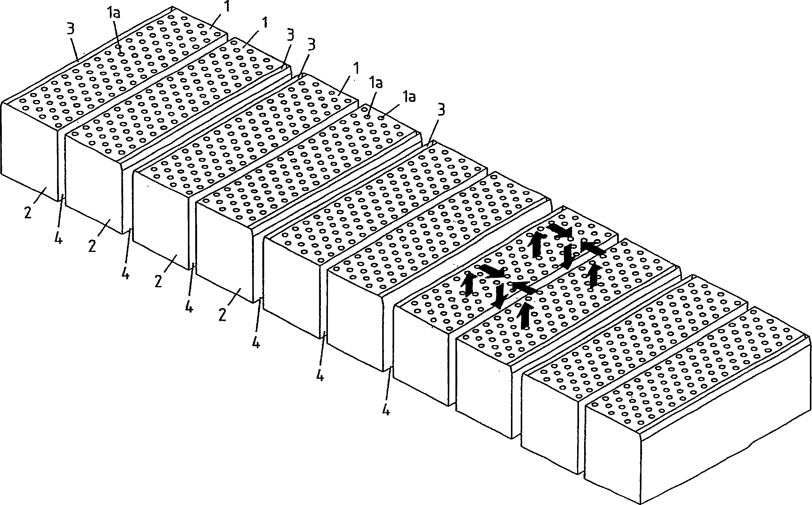
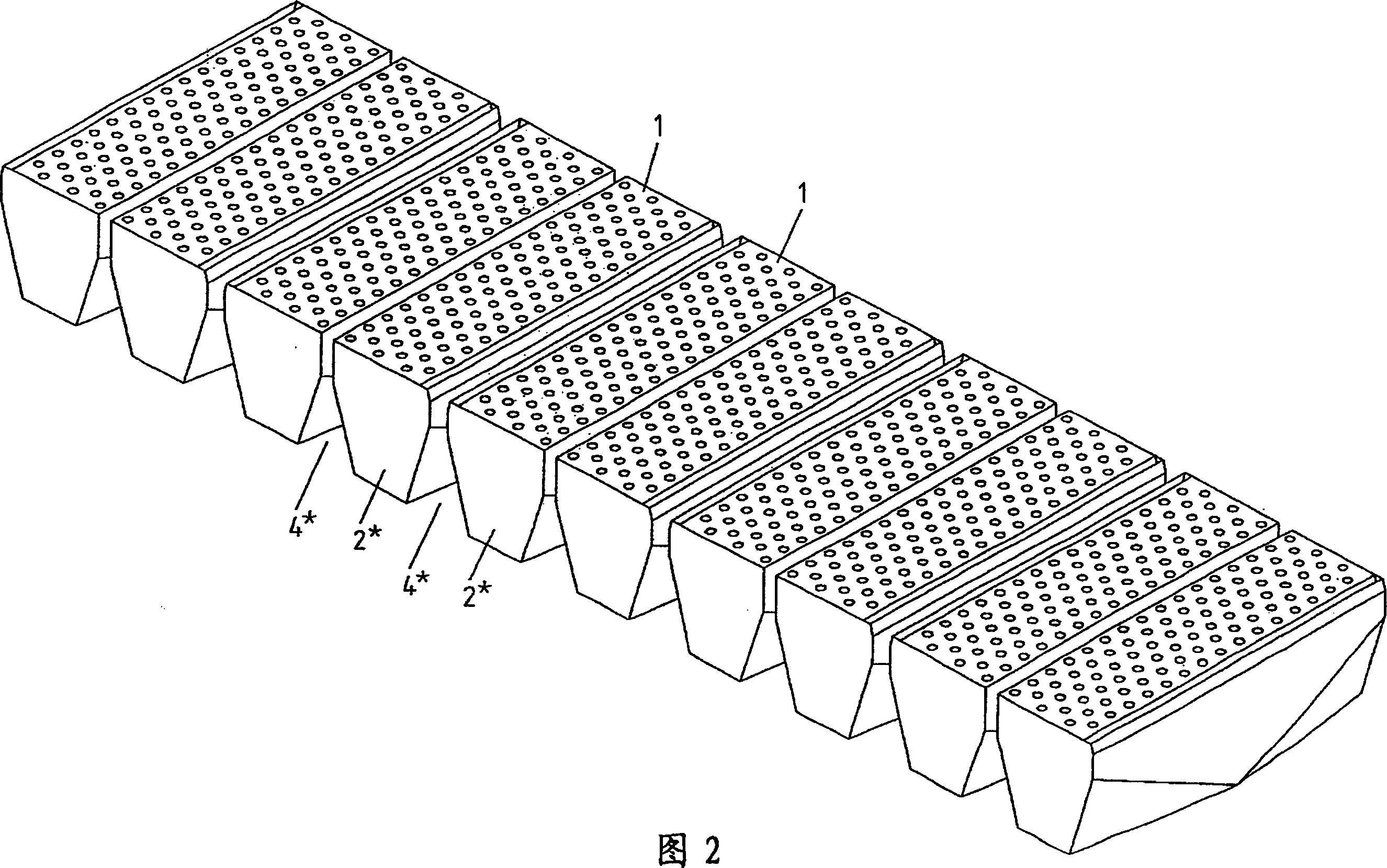
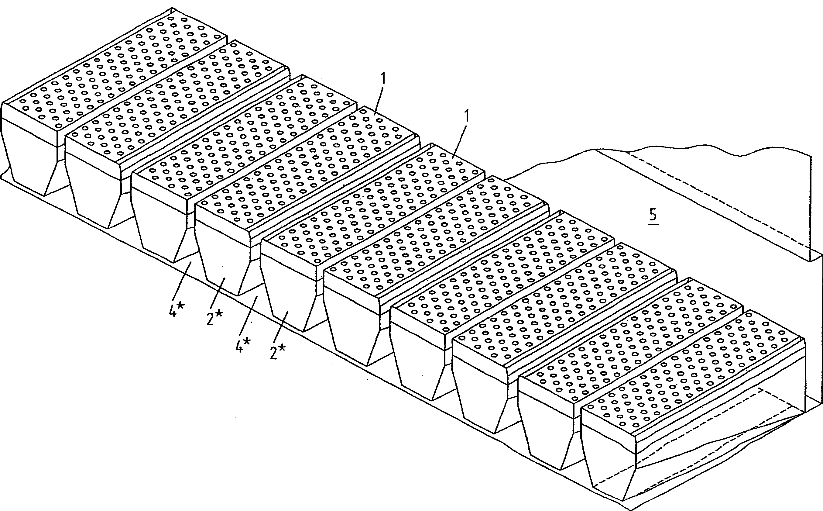
[0017] according to figure 1 The nozzle system comprises a total of ten consecutive nozzle surfaces 1 along the conveying direction (not shown) of the metal strip. A nozzle system (not shown) of the same type may be arranged above the metal strip. These nozzle surfaces 1 are each arranged on the upper side of nozzle boxes 2 , which are connected on the bottom side to a fan, not shown. The nozzle surfaces 1 also each have a plurality of, in this embodiment circular, nozzle openings 1 a through which the process gas flowing from the fan into the nozzle box 2 flows onto the metal strip. Channels 4 are formed between the nozzle boxes 2 through which the process gas flowing onto the surface of the metal strip flows out again. According to the invention, the nozzle surface 1 is divided into groups, in this embodiment into pairs, by slit-like nozzles 3 extending perpendicularly to the conveying direction of the material which is also arranged on the upper side of the nozzle box 2 ....


PUM


Abstract

The invention relates to a nozzle system for the treatment of web-shaped material, especially metal strip, comprising nozzle surfaces (1, 1*, 1**), each having a plurality of nozzle apertures (1a), disposed at least on one side of the web-shaped material and located successively in the direction of transport of the web-shaped material. The nozzle system is characterized in that the nozzle surfaces (1, 1*, 1**) are bordered in groups by slit-shaped nozzles (3, 3*, 3**) running transverse to the direction of transport of the material.

Description

technical field [0001] The invention relates to a nozzle system for processing web material, especially metal strip, which system comprises nozzle surfaces, each nozzle surface having a Set of multiple nozzle holes. Background technique [0002] Nozzle systems of this type are known in many designs from the prior art. They are used, for example, in suspension-strip furnaces, in which metal strips are subjected to heat treatment in a contactless manner, for example to stress-relief annealing. They are also used in textile technology in which the material web is guided in suspension after printing or in coating technology for drying purposes after a coating device. Typically in such applications the web material is guided horizontally and in a suspended manner under the action of process air flows from nozzle surfaces arranged above and below the web. The airflow impinging on the surface of the mesh material is then recirculated through the recirculation channels formed bet...

Claims


Application Information

Patent Timeline
IPC IPC(8): C21D9/64B65H23/24B05C13/02
Inventor 拉尔夫·博林克尔齐茨托夫·霍尔尼希克劳斯·施米茨温弗里德·佐默艾森
Owner OTTO JUNKER GMBH
Why Eureka
Try Eureka