

Centrifugal fan
A centrifugal fan and fan blade technology, which is applied to the components of pumping devices for elastic fluids, non-variable volume pumps, machines/engines, etc., can solve the problem that the overall airflow characteristics of the combined centrifugal fan 2 is not improved, and the material cost Waste and other problems, to achieve the effect of increasing wind pressure, improving airflow characteristics, and reducing airflow counterflow
- Summary
- Abstract
- Description
- Claims
- Application Information
AI Technical Summary
Problems solved by technology
Method used
Image

Examples
no. 1 example
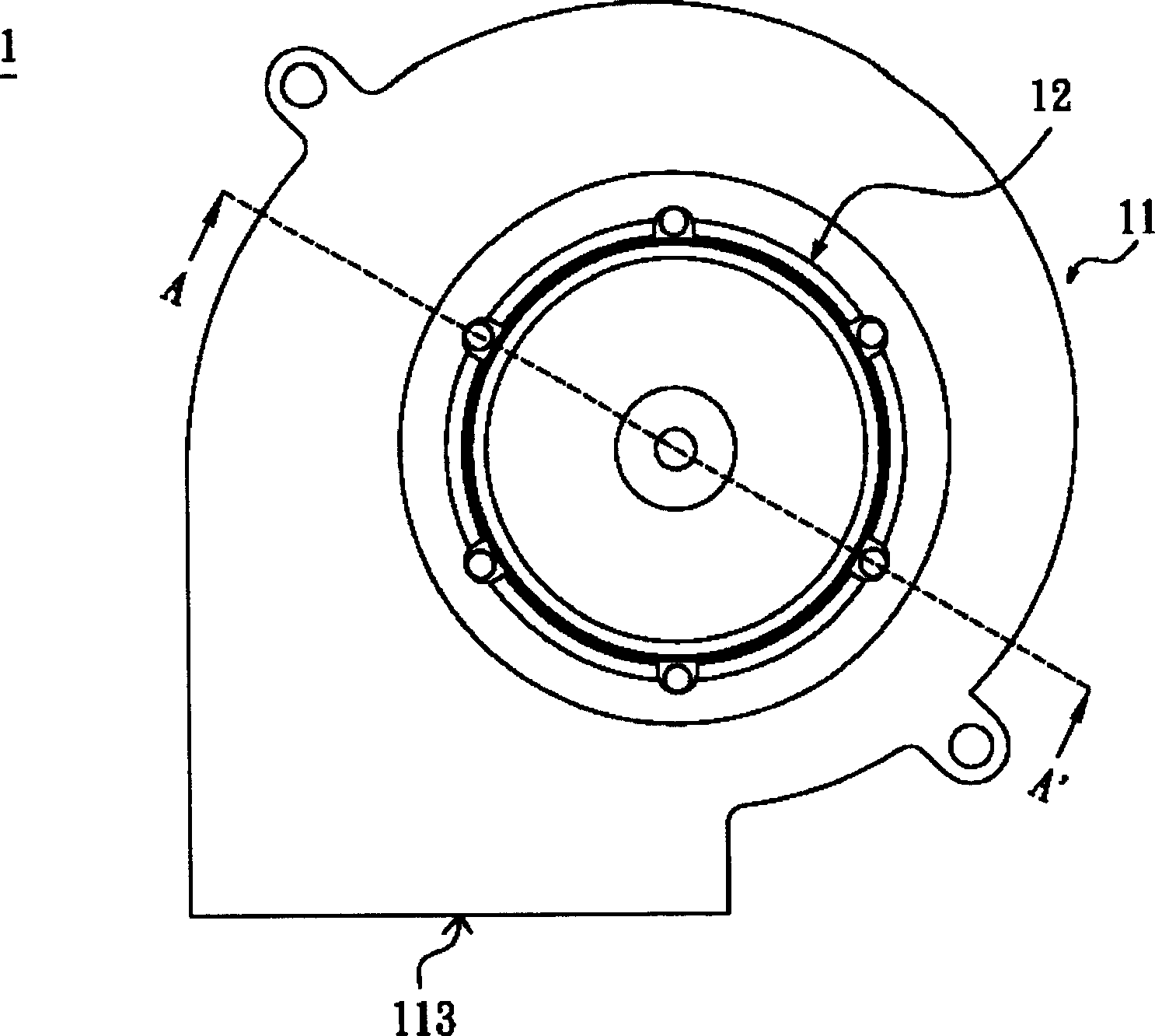
[0045] FIG. 5 is a schematic top view of the centrifugal fan according to the first embodiment of the present invention. As shown in FIG. 5 , the centrifugal fan 3 includes a casing 31 and a plurality of impellers 32 .
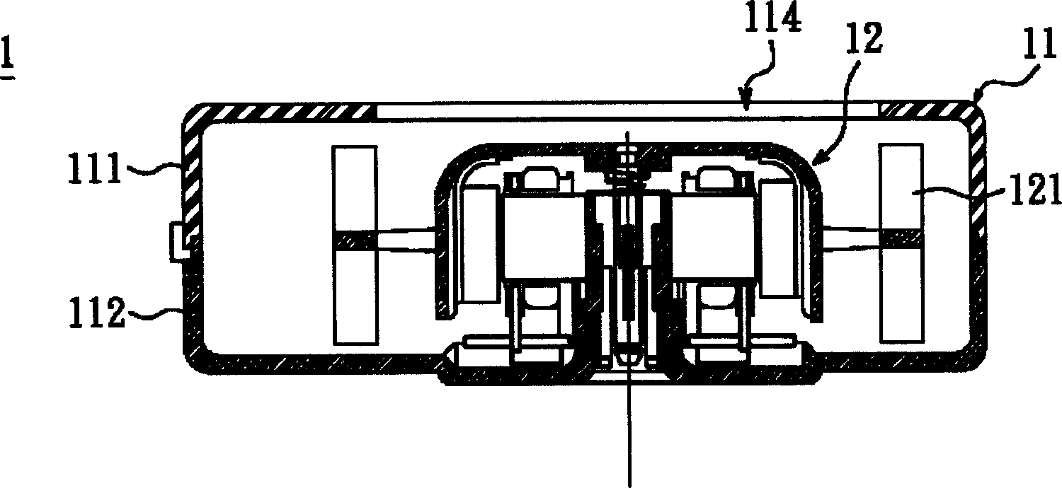
[0046] Figure 6 It is a schematic sectional view of Fig. 5 along the line B-B', such as Figure 6 As shown, in this embodiment, the casing 31 has two air inlets 311 , and each air inlet 311 corresponds to each impeller 32 . In addition, the shell system has an air outlet 312 , so that the air flow enters the impeller 32 through multiple air inlets 311 , is driven by the blades of the impeller 32 , and then is sent out through a single air outlet 312 .
[0047] The impeller 32 is accommodated in the casing 31 , and there is a flow collecting channel 33 between the impeller 32 and the casing 31 , and the impeller 32 has a plurality of fan blades 321 respectively. Wherein, the casing 31 has a peripheral portion 312 at the air inlet 311, and the peripheral por...
no. 2 example
[0050]Next, please refer to FIG. 7 , which is a schematic top view showing a centrifugal fan according to a second embodiment of the present invention. As shown in FIG. 7 , the centrifugal fan 4 includes a casing 41 and two impellers 42 . A plurality of impellers 42 are accommodated in the casing 41 , and a flow collecting passage 43 is provided between the impellers 42 and the casing 41 .
[0051] As shown in Figure 7, the casing 41 has an air outlet 412, and the two impellers 42 are arranged in a straight line, and the center line of the impeller 42 and the section of the air outlet 412 have an included angle Θ, wherein the included angle Θ is is an acute angle. That is to say, the configuration of the two impellers 42 is asymmetrically arranged in the casing 41, which can reduce the phenomenon that the airflow driven by each impeller 42 interferes with each other, so a plurality of impellers 42 are arranged asymmetrically in the casing. In the body 41, the decline of the ...
no. 3 example
[0057] Figure 11 It is a schematic top view of a centrifugal fan according to the third embodiment of the present invention. Such as Figure 11 As shown, the two impellers 42 in the centrifugal fan 4 are arranged in a straight line, and the center connection of the plurality of impellers 42 is about 90 degrees to the air outlet 412 .
[0058] Centrifugal fan 4 also can have more than two impellers 42, such as Figure 12 as shown, Figure 12 It is a schematic top view of another centrifugal fan according to the third embodiment of the present invention. Please also refer to Figure 11 and Figure 12 , the centrifugal fan 4 has three impellers 42 , and a blocking member 44 is arranged between every two impellers 42 . There is a common collector flow passage 43 among the plurality of impellers 42 , and since the centrifugal fan 4 has a plurality of impellers 32 connected in series, the overall performance of the centrifugal fan 4 can be increased.
[0059] The centrifugal...
PUM
 Abstract
Description
Claims
Application Information