Pump capable of eliminating air resistor

A technology of air resistance and vacuum pumps, which is applied to pumps, parts of pumping devices for elastic fluids, and drive pumps, etc. It can solve the problems of complex pumps and inconvenient clutch operating mechanisms, and achieve simple and reliable control, small size, Versatile effect

Active Publication Date: 2007-01-31
CHONGQING HAIFU MEDICAL TECH CO LTD
View PDF1 Cites 4 Cited by
  • Summary
  • Abstract
  • Description
  • Claims
  • Application Information

AI Technical Summary

Problems solved by technology

This structure can solve the problem of air resistance, but when the power of the pump is small and the volume is smal

Method used


Image

  • Pump capable of eliminating air resistor
  • Pump capable of eliminating air resistor
  • Pump capable of eliminating air resistor

Examples


Example Embodiment

[0015] Example 1:

[0016] The present invention will be described in further detail below in conjunction with embodiments and drawings.

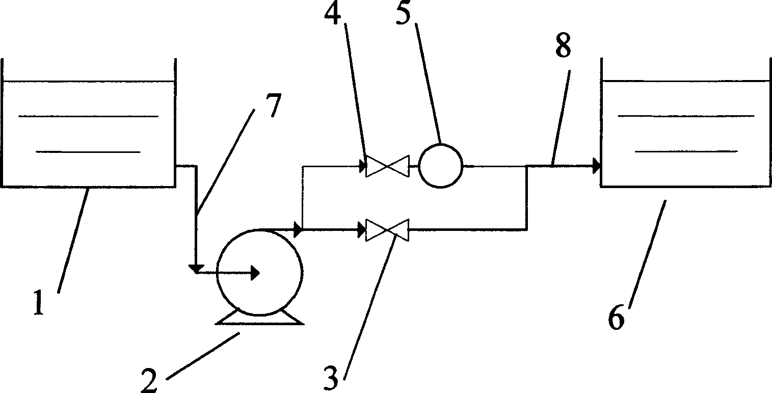
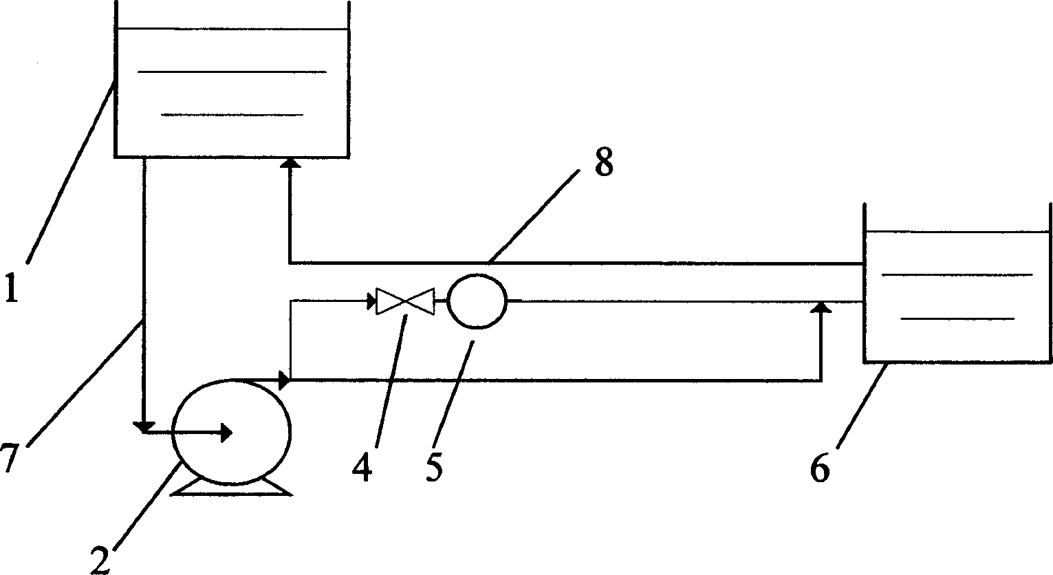
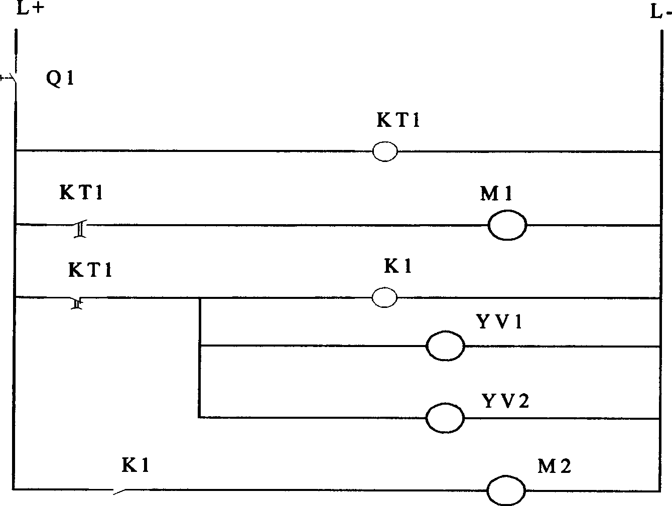
[0017] Such as figure 2 As shown, in this embodiment, the combined pump device includes a water tank 1, a pump 2, a vacuum pump 5, a water tank 6, and a control circuit. The inlet and outlet of the pump 2 are connected to the water inlet pipe 7 and the water outlet pipe 8 respectively, and the water inlet pipe 7 and the water outlet pipe 8 are respectively connected to the water tank 1 and the water tank 6, wherein the pump 2 is a magnetic pump, and the vacuum pump 5 is a micro vacuum pump. Since the water path in this embodiment is a circulating water path, the water tank 6 is connected to the water tank 1, and a micro vacuum pump M2 is connected in parallel to the water outlet pipe 8. A solenoid valve YV is connected to the inlet pipe of the vacuum pump 5 1 3. The solenoid valve YV 1 The circuit of 3 is connected in parallel with the interme...


PUM


Abstract

The invention relates to a pump capable of eliminating vapour lock, which includes a pump, whose inlet and outlet are connected the liquid inlet and outlet tubes separately. A vacuum pump is connected in parallel with the liquid outlet tube and a control device is used for controlling the start and stop of the pump and the vacuum pump.

Description

technical field [0001] The invention belongs to the technical field of liquid pumps, and in particular relates to a water pump capable of eliminating air resistance. Background technique [0002] In the existing water supply system, a large number of water pumps and magnetic pumps are usually used. These pumps rely on the principle of atmospheric pressure to supply water, so the problem of air resistance in the pipeline often occurs, that is, if there is air in the pump body or the water inlet circuit of the water pump , the pump will not work properly. The common method is to place the pump below the liquid surface and let the liquid flow into the pump body by gravity. However, when the pipeline is long and thin and the power of the pump is small, the air resistance phenomenon is obvious. [0003] A utility model patent with the patent publication number CN2533298Y discloses a strong self-priming pipeline pump, which is a set of elastic diaphragm shock-type suction and exh...

Claims


Application Information

Patent Timeline
IPC IPC(8): F04D29/66F04D9/02
Inventor 王智彪李涛胡政林涛
Owner CHONGQING HAIFU MEDICAL TECH CO LTD
Why Eureka
Try Eureka