
Ampule cutting apparatus

A cutting device and ampoule technology, applied in glass cutting devices, electric operating devices, packaging, etc., can solve problems such as head H injury

Inactive Publication Date: 2007-02-07
SAMSUNG GWANGJU ELECTRONICS CO LTD
View PDF0 Cites 5 Cited by
  • Summary
  • Abstract
  • Description
  • Claims
  • Application Information

AI Technical Summary

Problems solved by technology

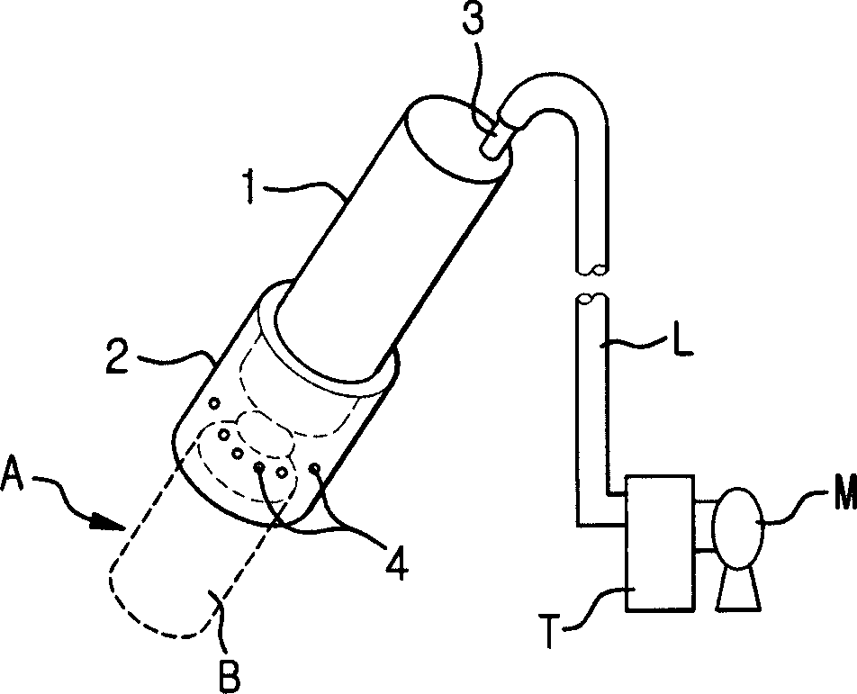
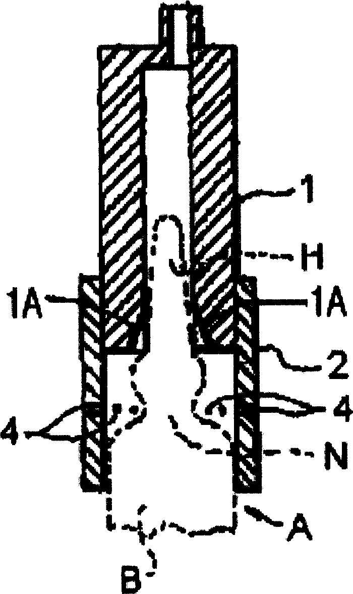
Therefore, the user may accidentally be injured by the cut head H

Method used


Image

  • Ampule cutting apparatus
  • Ampule cutting apparatus
  • Ampule cutting apparatus

Examples


Embodiment Construction

[0056] Now, the ampoule cutting device according to the present invention will be described in detail with reference to the accompanying drawings.

[0057] Figure 3A is a perspective view showing an ampoule cutting device according to the present invention, Figure 3B is a schematic side sectional view showing the internal structure of the ampoule cutting device according to the present invention.

[0058] refer to Figure 3A and Figure 3B , the ampoule cutting device includes a box-shaped casing 10 , a cyclone object collecting unit 20 and an ampoule cutting unit 30 arranged at the top of the inner portion of the casing 10 . The cyclone object collection unit 20 is configured to suck and collect the heads H and fragments of the cut ampoules (hereinafter, both individually and collectively are referred to as 'objects'). The ampoule cutting unit 30 for accommodating and cutting the head H of the ampoule is connected and coupled to the inlet 21 of the cyclone object collec...


PUM


Abstract

Disclosed is an ampule cutting apparatus including an ampule cutting unit for housing and cutting an ampule head, a object collecting unit for sucking the cut ampule head (H) and minute flakes generated in the ampule cutting operation with the air, and separating the objects from the air, a negative pressure generating device for applying a negative pressure to the object collecting unit; and a collecting unit for collecting the objects sucked by the object collecting unit.

Description

[0001] This application claims the benefit of Korean Patent No. 2005-71533, filed on Aug. 5, 2005, the entire contents of which are incorporated herein by reference. technical field [0002] The present invention relates to an ampoule cutting device, and more particularly, to an ampoule cutting device using a cyclone object collecting device. Background technique [0003] Typically, after the neck of the ampoule is cut, the injection in the ampoule is aspirated through the needle of the syringe. When the neck of the ampoule is cut, the fine glass fragments (or glass powder) generated at the neck part fall outside the ampoule and partially fall into the ampoule. More specifically, since the internal pressure of the sealed ampoule is kept below atmospheric pressure, the glass fragments generated during the cutting operation of the ampoule neck are likely to fall into the ampoule. [0004] In the case where an injection containing fine g...

Claims


Application Information

Patent Timeline
Patent Type & Authority Applications(China)
IPC IPC(8): B67B7/82B67B7/88B67B7/92
CPCY10T83/207B26F3/002C03B33/06B67B7/92B26D7/1854B26D7/1863A61J1/06B65D17/50
Inventor 吴长根徐知元
Owner SAMSUNG GWANGJU ELECTRONICS CO LTD
Learn More