Manufacturing equipment of hot pipe device and its application

A technology for manufacturing equipment and devices, which is applied to heat pipe device manufacturing equipment and its application fields, can solve the problems of low production cost, long vacuuming time, increased processing steps, etc., and achieves high vacuum retention, high degree of automation, and simple equipment structure. Effect

Inactive Publication Date: 2010-04-28
李建民
View PDF5 Cites 0 Cited by
  • Summary
  • Abstract
  • Description
  • Claims
  • Application Information

AI Technical Summary

Problems solved by technology

The heat removal method is used in the heat pipe production of industrial heat exchangers, but this heat removal method is to heat the heat pipe after filling the working medium into the heat pipe cavity, the working medium is heated to form a gas, and the gas inside the cavity Take it out of the cavity, and then cool the cavity to form a vacuum; but this method has many shortcomings, first of all, it is impossible to control the exact exhaust time of each heat pipe, and it is also impossible to judge the vacuum degree of the heat pipe, which can only be judged by experience , so the scrap rate is high and the reliability is poor. Secondly, the vacuum formed by it is limited, it is difficult to form a high vacuum, and it cannot be produced for heat pipe devices that require high vacuum. However, this method is simple and easy to operate, and the production cost is low; Vacuum method, this method is mainly used for the production of small heat pipes, because the investment in vacuum equipment is large, and the pumping time for large cavities is long, which cannot meet the needs of industrial production;
[0004] There are basically two vacuum filling methods in the prior art. One is to use the heat exhaust method to fill the working medium into the cavity and heat it first. This method cannot form a high vacuum and is therefore not suitable for the production of small heat pipes. Secondly, the use of vacuum equipment is to first vacuumize the cavity, and then fill the cavity with the working medium, and the vacuum and liquid-filled pipes are carried out with the same nozzle, but none of the existing technologies can achieve pumping. Vacuum filling can realize batch manufacturing or equipment that can realize automatic control, but it is difficult to realize batch manufacturing and production of heat pipes. There are many defects in the existing heat pipe manufacturing methods no matter whether the heat exhaust method or the vacuum method is adopted;
[0005] After the vacuuming and liquid filling are completed, the existing method uses two methods to seal the heat pipe. For the heat exhaust method, the tapered pin is used to drive the tapered pin into the vent hole, and welding is applied to complete the sealing. For the vacuum method, the method of cold welding pliers is used to clamp the vacuum tube (liquid-filled tube) with a pliers at room temperature and then cut the tube, and complete the sealing after applying welding; for the tapered pin sealing method, it is impossible to form a high Vacuum degree, and the airtight opening is relatively large, so it cannot be used in small heat pipes; for the cold welding method, because no matter what material the heat pipe is made of, cold welding cannot achieve true airtightness, and it is often required to weld immediately after the cold welding is completed. Otherwise, the degree of vacuum will be lost. This method cannot achieve complete vacuum sealing. Moreover, from the perspective of production, welding equipment is needed after cold welding, which increases the processing procedures and increases the manufacturing cost.
[0006] The production methods of existing heat pipe devices limit and hinder the general adoption of heat pipe technology. Although the cost of adopting the heat exhaust method is low, it is difficult to form a high vacuum and is difficult to be widely used, and it cannot be applied to high vacuum heat pipe devices. method, because its vacuuming, filling and airtightness adopt the existing methods, making it difficult to master, high production cost and low efficiency;

Method used


Image

  • Manufacturing equipment of hot pipe device and its application
  • Manufacturing equipment of hot pipe device and its application
  • Manufacturing equipment of hot pipe device and its application

Examples


Embodiment Construction

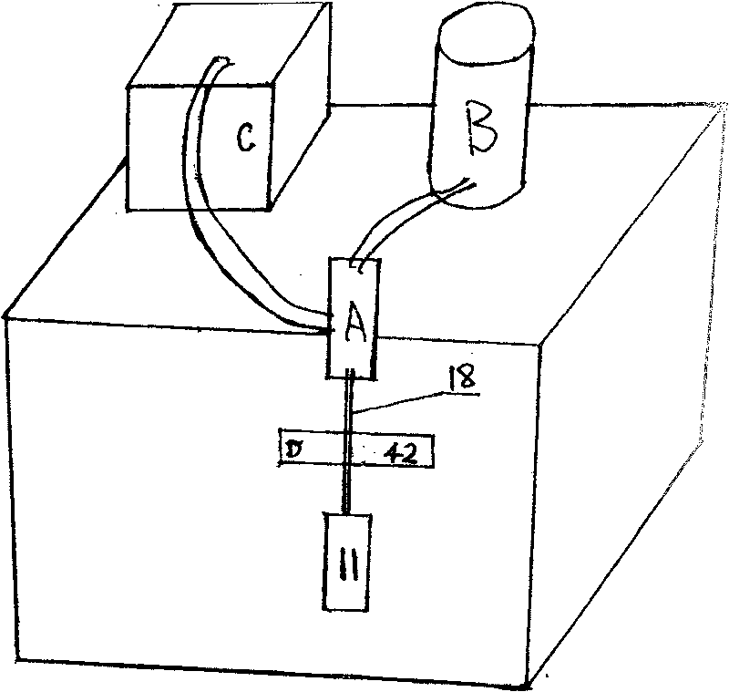
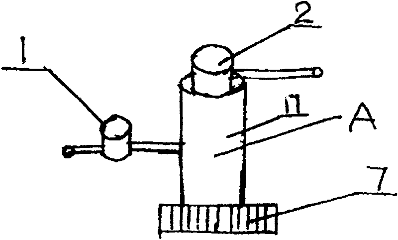
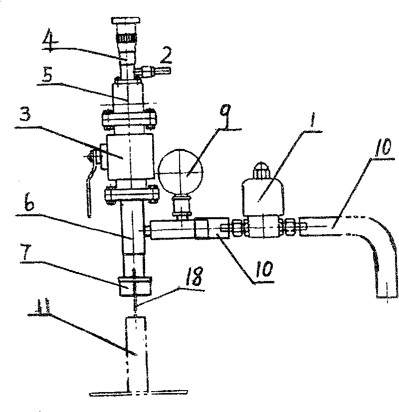
[0037] see figure 1 , a heat pipe device manufacturing equipment is characterized in that: it is composed of at least one vacuum filling valve group A, at least one working medium filling system B, at least one vacuum obtaining device C, and at least one sealing device D, and the vacuum obtaining device C The vacuum valve 1 is connected to the chamber of the vacuum filling valve group A, the working medium filling system B is connected to the chamber of the vacuum filling valve group A through the valve 2, and the sealing clamp of the sealing device D is located in the vacuum filling At the bottom of the valve group A, the vacuum filling tube 18 of the processed workpiece 11 is inserted into the inside of the rubber ring 16 through the clamping ring 7, and the processed workpiece 11 is connected with the vacuum filling valve group A by tightening the clamping ring 7. Airtight, the sealing device D is located at the bottom of the clamping ring 7, and the vacuum filling tube 18 ...


PUM


Abstract

The present invention relates to one kind of heat pipe manufacturing apparatus and its application. The heat pipe manufacturing apparatus consists of a vacuum valve assembly, a work medium filling system, a vacuumizing unit, a sealing unit, a frame and other parts. It may be used in completing vacuumizing, filling and sealing. It may be a single machine or a machine combination with several work sites, and may be manually operated, semi-automatic or automatic. It is used in manufacturing heat pipe devices in high efficiency and high quality.

Description

technical field [0001] The heat pipe device manufacturing equipment and its application relate to the manufacturing equipment and application of heat pipe devices such as heat transfer, heat dissipation, heat collection, heat storage, heat control, heat management, and heating. Background technique [0002] Heat pipes have been widely used in industrial production. [0003] The manufacturing method of the heat pipe device mainly consists of vacuuming, liquid filling, and sealing. The existing methods for forming a vacuum are heat exhaustion and vacuuming. The heat removal method is used in the heat pipe production of industrial heat exchangers, but this heat removal method is to heat the heat pipe after filling the working medium into the heat pipe cavity, the working medium is heated to form a gas, and the gas inside the cavity Take it out of the cavity, and then cool the cavity to form a vacuum; but this method has many shortcomings, first of all, it is impossible to cont...

Claims


Application Information

Patent Timeline
Patent Type & Authority Patents(China)
IPC IPC(8): B23P15/26B21D41/04B67C7/00
Inventor 李建民
Owner 李建民
Why Eureka
Try Eureka