Chip dynamic tracing method of microprocessor

A dynamic tracking and microprocessor technology, applied in microprocessors and other microprocessor fields, can solve problems such as increasing the difficulty of design and production costs

Inactive Publication Date: 2007-02-14
SHANGHAI UNIV
View PDF0 Cites 31 Cited by
  • Summary
  • Abstract
  • Description
  • Claims
  • Application Information

AI Technical Summary

Problems solved by technology

Therefore, for on-chip dynamic tracking, integrating a memory for dynamic tracking inside the processor will increase the difficulty of design and production costs, etc.

Method used


Image

  • Chip dynamic tracing method of microprocessor
  • Chip dynamic tracing method of microprocessor
  • Chip dynamic tracing method of microprocessor

Examples


Embodiment Construction

[0062] A preferred embodiment of the present invention is described in detail as follows in conjunction with accompanying drawing:

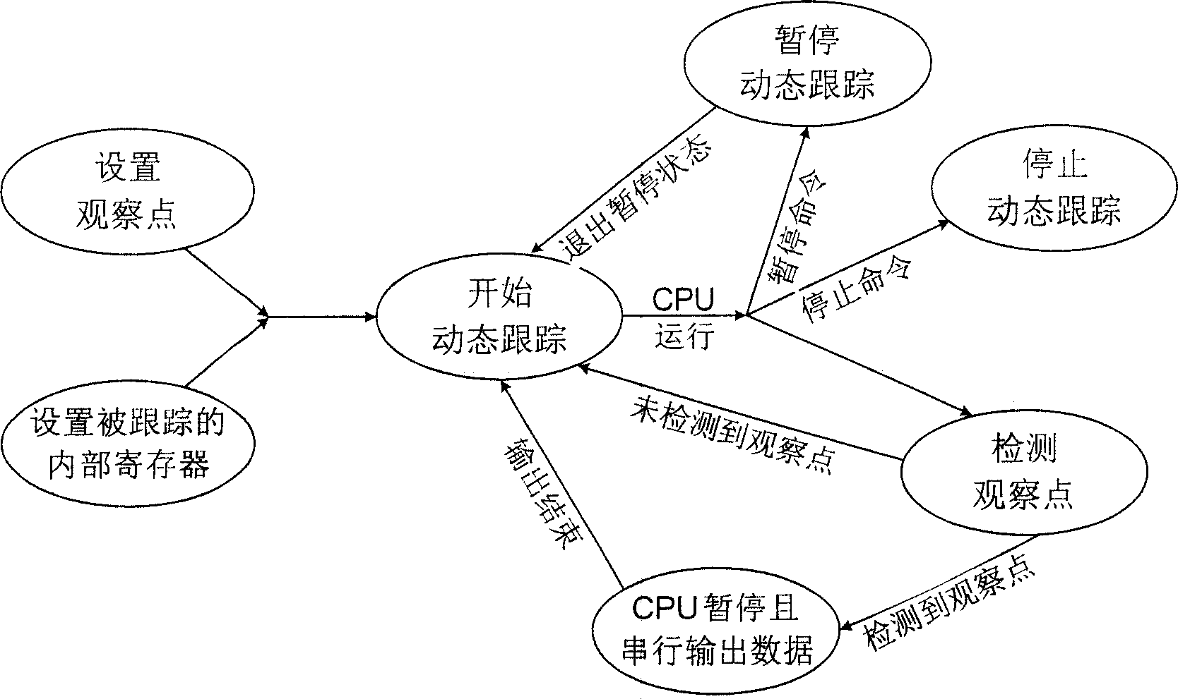
[0063] The on-chip dynamic tracking method of this microprocessor adopts the following workflow (see figure 1 ) to realize the dynamic tracking of the processor running process:

[0064] 1) Several observation points in the program are specified by the debugger. In this example, n=8 is set, and there are 8 watchpoint address registers WPi (0-7) in total. Therefore, the debugger can arbitrarily set 0-8 watchpoints.

[0065] 2) Internal registers that need to be traced and recorded at each observation point are specified by the debugger. In this example, 24 commonly used internal registers are set for selection, and the selection of these 24 internal registers is independent of each other. The debugger can select 1 to 24 internal registers that need to be tracked and recorded according to the situation.

[0066] 3) Start the process of dynamic ...


PUM


Abstract

This invention relates to an on-chip tracing method of a microprocessor, which sets some positions as viewing points in the execution process of a program by an on-chip tracer (OCT), then traces, records and outputs the information of the assigned internal registers at these points used in the field of 8051 serial microprocessor or other microprocessor fields.

Description

technical field [0001] The invention relates to an on-chip dynamic tracking method of a microprocessor, which can be applied to 8051 series single-chip microprocessors, and can also be applied to other microprocessors and microprocessor fields. Background technique [0002] Dynamic Trace (Dynamic Trace) refers to the process of recording the track information of program running in real time, and transmitting this information to an external debugging tool for analysis and debugging by some means. In the debugging and development process of embedded systems with microprocessors as the core, in order to facilitate the capture of high-speed signals and debug the processor, such as checking, recovering, and modifying according to the program execution history, it is necessary to record the high-speed running time of the processor. traces of. Therefore, in most devices such as logic analyzers and in-circuit emulators, there are tracking components used to dynamically track the ru...

Claims


Application Information

Patent Timeline
Patent Type & Authority Applications(China)
IPC IPC(8): G06F11/36
Inventor 胡越黎熊兵孙斌
Owner SHANGHAI UNIV
Why Eureka
Try Eureka