Relay amplification device with transmit-receive function and transmit-receive control method

A technology for amplifying devices and transmitting and receiving control, which is applied in radio transmission systems, electrical components, transmission systems, etc., and can solve problems such as the inability to dynamically switch the working status of uplink and downlink power controllers

Active Publication Date: 2007-02-14
DATANG MOBILE COMM EQUIP CO LTD
View PDF0 Cites 27 Cited by
  • Summary
  • Abstract
  • Description
  • Claims
  • Application Information

AI Technical Summary

Problems solved by technology

[0006] The problem to be solved by the present invention is to propose a relay amplification device with a transceiver control function and a transceiver control method, so as to solve the probl

Method used


Image

  • Relay amplification device with transmit-receive function and transmit-receive control method
  • Relay amplification device with transmit-receive function and transmit-receive control method
  • Relay amplification device with transmit-receive function and transmit-receive control method

Examples


Embodiment Construction

[0054] Below we will describe in detail the best implementation of the present invention with reference to the accompanying drawings. First of all, it should be pointed out that the meanings of the terms, words and claims used in the present invention should not be limited to their literal and ordinary meanings, but also include meanings and concepts consistent with the technology of the present invention, because It is up to us, as inventors, to define terms appropriately in order to best describe our inventions. Therefore, the configurations given in this specification and the accompanying drawings are only preferred implementations of the present invention, rather than enumerating all technical characteristics of the present invention. We need to recognize that there are various equivalents or modifications that could replace ours.

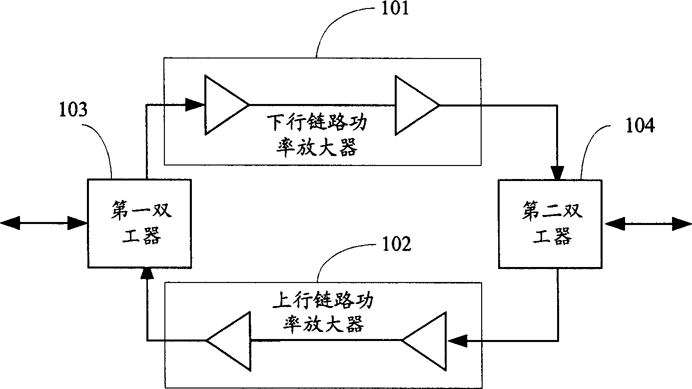
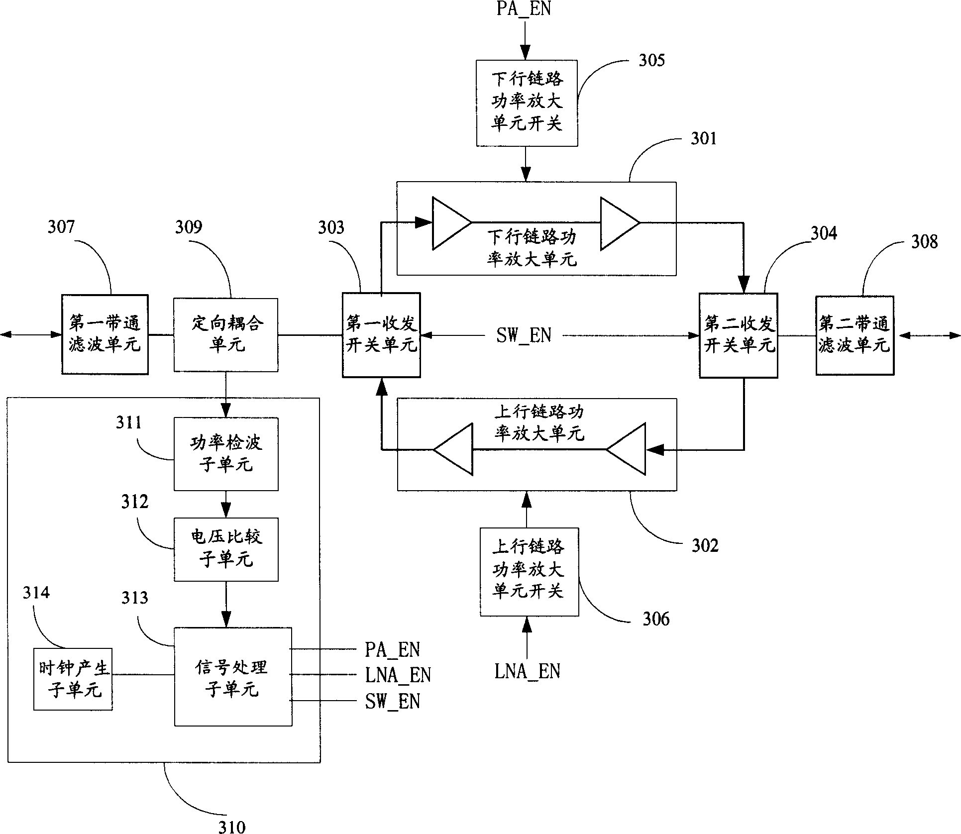
[0055] The basic principle of the relay amplification device of the present invention is as image 3 As shown, it includes: a downlink power...


PUM


Abstract

This invention discloses a relay amplification device with the TR control function including: a coupling unit and a working state control unit, in which, the coupling unit couples the RF signals from the base station to a first TR switch unit and a working state control unit separately, which controls the conduction of the up-link of the relay amplifying device based on the RF signal received from the base station, its power amplification, cut-off and close of the power amplifier of the down-link or controls the down-link conduction and its power amplifier, the cut-off of the up link and shut of its power amplifier, besides, this invention also provides a control method for TR signals of the relay amplification device.

Description

technical field [0001] The invention relates to a time-division multiplexing wireless communication system, in particular to a relay amplifying device and a transmitting-receiving control method in the time-division multiplexing wireless communication system. Background technique [0002] In a wireless communication system, since the wireless terminals may be distributed widely, the wireless signals of the base station can only cover the wireless terminals within a certain range. If it is necessary to cover a larger range, it is necessary to add a relay amplifier (also called a trunk amplifier) ​​between the base station and the far coverage area to perform relay amplification on the wireless signal. [0003] Depending on the working mode of the wireless communication system, the working principle of the applied relay amplifier is also different. Currently, the uplink and downlink working modes in the wireless communication system are mainly FDD (Frequency Division Duplex, ...

Claims


Application Information

Patent Timeline
IPC IPC(8): H04B7/212
Inventor 段滔付从伟王忠勇
Owner DATANG MOBILE COMM EQUIP CO LTD
Why Eureka
Try Eureka