[0032] In the following description, application of the present invention to radio communication terminals including all forms of radio transceivers, such as mobile telephones, radio calling devices or personal digital assistants (PDAs), is described.
[0033] The radio communication terminal according to the present invention may be of the GSM850, GSM900, DCS (Digital Communication System), UMTS (Universal Mobile Telecommunications System) type, or may be a DECT (Digital European Cordless Communication) type telephone. This terminal can also integrate GPS (Global Positioning System) or Wi-Fi (Wireless Fidelity) functions.
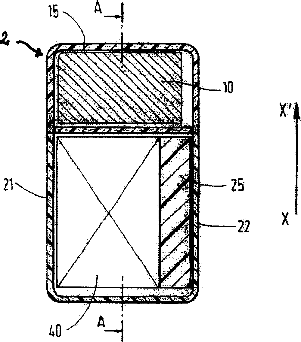
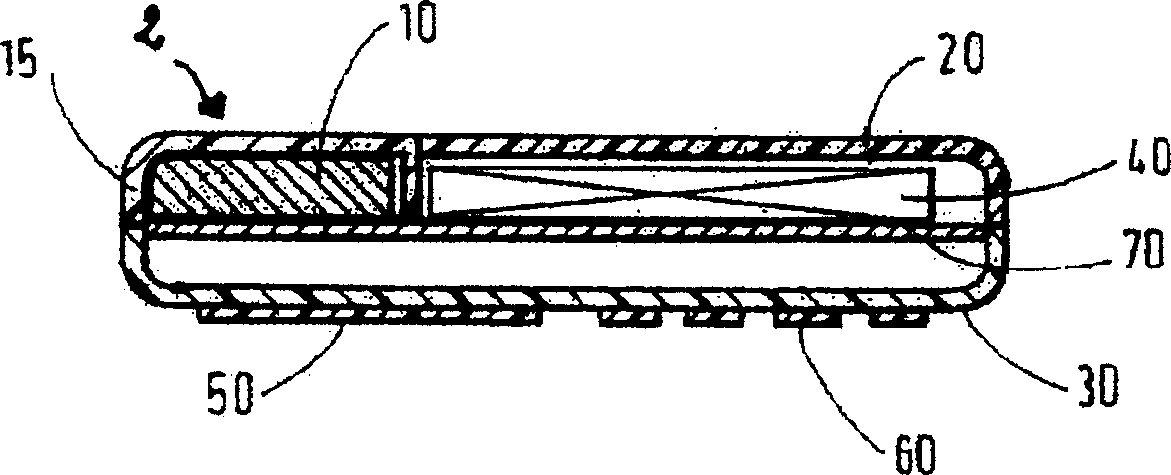
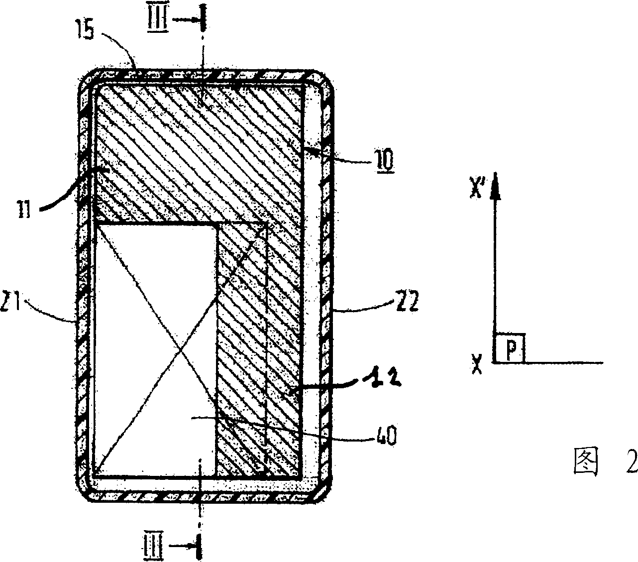
[0034] The terminal of FIG. 2 is formed from the housing with two side walls parallel to the axis in the X-X' direction: a first wall 21 and a second wall 22. In addition, there are two walls perpendicular to the axis of the X-X' direction, these walls define the front shell 30 and the rear shell 20 of the terminal.
[0035] Under the rear case 20, the antenna 10 and the energy storage device 40 adjacent to the antenna 10 are placed.
[0036] The energy storage device 40 has an upper surface extending in the plane P. This plane P is parallel to the plane formed by the inner surface of the rear case 20 of the terminal.
[0037] The energy storage device 40 supplies the electrical energy required for operation to the components of the terminal. These parts are the printed circuit 70 , the antenna 10 , the display screen 50 and the keyboard 60 .
[0038] The energy storage device 40 occupies the first space, the battery space provided to it.
[0039] The overall size of this battery space is smaller than the inner surface of the rear shell 20 of the housing, thus forming a free space around the energy storage device 40 .
[0040] In this embodiment, the free space consists of the following parts:
[0041] - located in the prior art Figure 1A the space below the antenna hatch 15, i.e. in the upper rear portion, for example at the upper 1/3 of the rear of the terminal along the longitudinal axis of the housing; and
[0042] - by prior art Figure 1A The space occupied by the plastic part 25 of the terminal is 2/3 behind the lower part of the terminal between the energy storage device 40 and the second wall 22 of the terminal.
[0043] In this embodiment, the longitudinal dimension of the energy storage device 40 is such that it occupies mainly the rear 2/3 of the terminal housing.
[0044] Since the current trend is to miniaturize parts, it is clear that the energy storage device 40 can be smaller and occupy less than 2/3 of the rear of the terminal. In this case, the empty space is larger.
[0045] According to the present invention, this empty space can be used, at least in part, to increase the space dedicated to the patch antenna 10 .
[0046] Thus, as shown in Figure 2 and image 3 As shown, the antenna 10 occupying earlier as a second space adjoining the battery space along the longitudinal axis of the housing also extends parallel to said plane P so as to occupy the free space surrounding the energy storage device.
[0047] The antenna space 10 is defined by the above-mentioned free space and at least a part of the space 26 located above the plane P between the energy storage device 40 and the rear case 20 of the terminal.
[0048] As shown in FIG. 2 , in the first embodiment, the antenna 10 is in an inverted L shape. With base 11 and rod 12.
[0049] The part of the antenna 10 forming the base 11 occupies the upper 1/3 part of the rear casing of the terminal, while the part forming the rod 12 occupies the lower part 2 of the rear casing of the terminal between the energy storage device 40 and the second wall 22 /3. In addition, the part forming the rod 12 preferably has the function of holding the energy storage device in place and replacing the part 25 used in the prior art (see Figure 1A ).
[0050] The microstrip of the patch antenna is made on the plane P between the energy storage device 40 and the rear housing 20 of the terminal.
[0051]Therefore, the overall volume of the antenna 10 is larger than that of prior art antennas.
[0052] This can increase the efficiency of the antenna to 50-60% in GSM900 mode (according to the standard, the required frequency is 880-960MHz). This also results in a frequency band that is closer to what the GSM standard requires, ie a bandwidth of about 7% (8.7% according to the standard requirement) instead of 6.5% of the prior art.
[0053] The larger size of the antenna 10 makes it easier to produce antennas with different resonant frequencies when it is desired to integrate GPS or WiFi functionality (resonant frequencies of 1.5 GHz and 2.5 GHz, respectively) in a GSM900 or DCS or UMTS type terminal.
[0054] like Figure 5 As shown, the overall size of the antenna 10 can be further increased by covering with some antenna volume all the free space around the battery, and in particular the space 26 above the plane P between the energy storage device 40 and the rear case 20 of the terminal volume.
[0055] another example Figure 5 and Image 6 As shown, for the rear shell 20 of the housing and the slightly convex terminal, the antenna volume between the energy storage device 40 and the rear shell 20 of the housing of the terminal can be larger.
[0056] like Figure 5 and Image 6 In order to do this, the microstrips of the patch antenna 10 are shown on surfaces whose contours are complementary to the inner surface of the rear housing.
[0057] In addition, the protrusion of the antenna on the printed circuit 70, ie the portion of the antenna 10 that is directly connected to the printed circuit 70, is larger than the antennas of the prior art, especially the terminals shown in Figs.
[0058] In the prior art, this protrusion was increased with the surface 25 covered by the plastic piece. The battery is fixed to the Figure 1B in the terminal shown.
[0059] This can further improve the efficiency of the antenna.
[0060] Therefore, the overall volume of the antenna 10 can be increased by occupying all the free space near the energy storage device 40 and between the energy storage device 40 and the rear case 20 of the terminal housing.
[0061] The current trend is for the surface and thickness of the energy storage device 40 to be smaller, and thus, the antenna 10 can take various forms.