Textile machine for manufacturing bobbins of twisted yarn

A textile machine and bobbin technology, which is applied to continuous winding spinning machines, spinning machines, textiles and papermaking, etc., can solve the problems of high cost, high operating cost, and difficult handling of creels, and reduce production costs , The effect of reducing maintenance costs

Inactive Publication Date: 2007-02-21
SAURER GMBH & CO KG
View PDF1 Cites 0 Cited by
  • Summary
  • Abstract
  • Description
  • Claims
  • Application Information

AI Technical Summary

Problems solved by technology

[0006] Another disadvantage of these two creel variants is that they are difficult or even impossible for persons of small stature to operate them, either due to (in the case of rigid creels) the operating depth and height or due to ( In the case of high and low creels) the operating height, on the other hand due to the relatively high weight of the feed bobbins, makes handling when assembling the creels more difficult
Another disadvantage that should also be mentioned is the high operating costs incurred by setting up the lifting table or lowering the mechanism
Another disadvantage lies in the conveyor belts extending in the longitudinal direction of the machine, the installation and maintenance of which entails considerable costs
Furthermore, since the conveyor belt is arranged between the workstations inside the machine, there is only a very limited degree of accessibility

Method used


Image

  • Textile machine for manufacturing bobbins of twisted yarn
  • Textile machine for manufacturing bobbins of twisted yarn
  • Textile machine for manufacturing bobbins of twisted yarn

Examples


Embodiment Construction

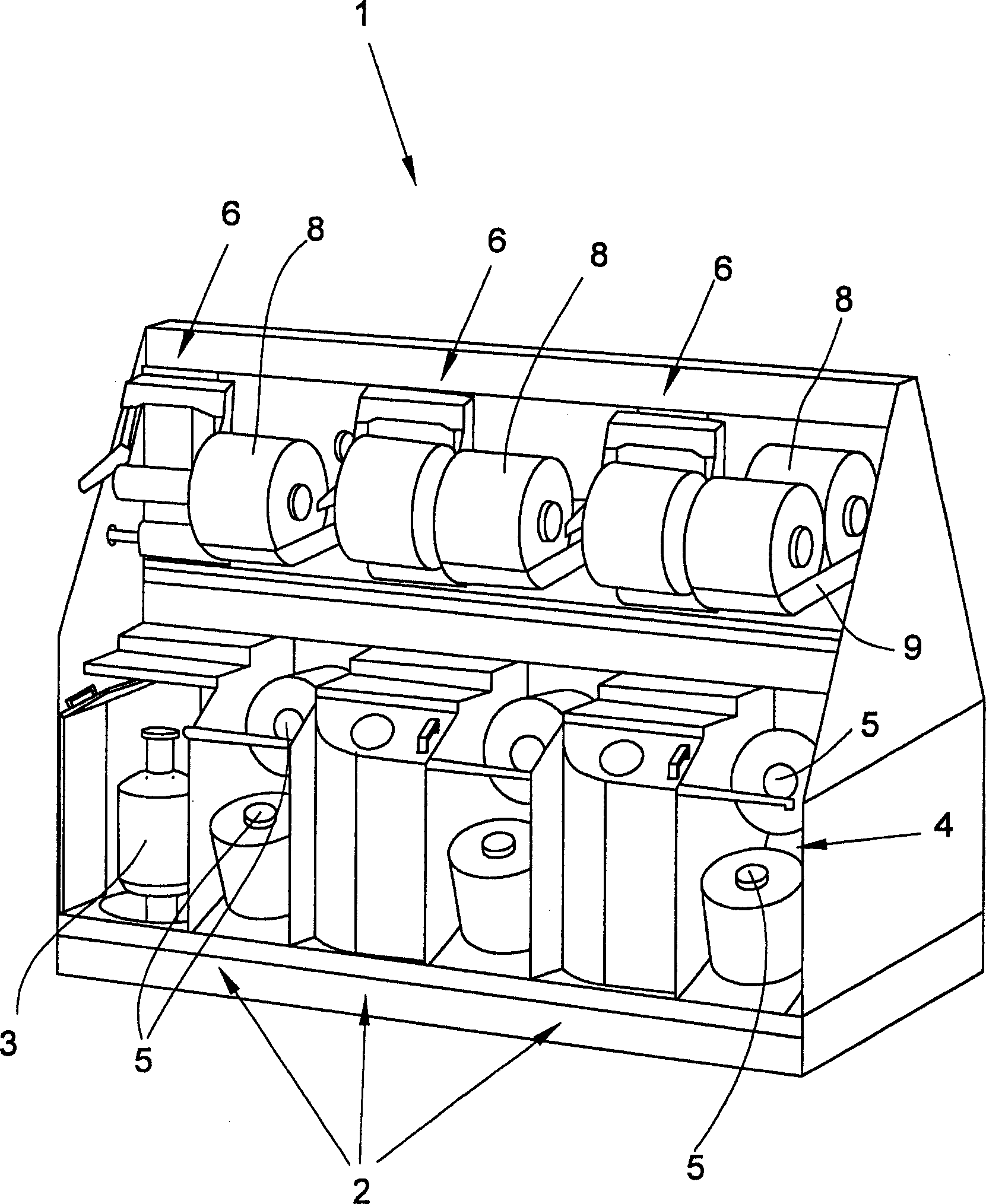
[0020] figure 1 A textile machine 1 for producing twisted yarn bobbins 8 according to the invention is shown. The textile machine 1 comprises a plurality of workstations 2 arranged on both sides of the textile machine 1 in the longitudinal direction of the machine. The workstation 2 comprises a spindle 3 and a creel 4 respectively. The creel 4 has at least two mounting pins 5 for receiving feed bobbins 7 .

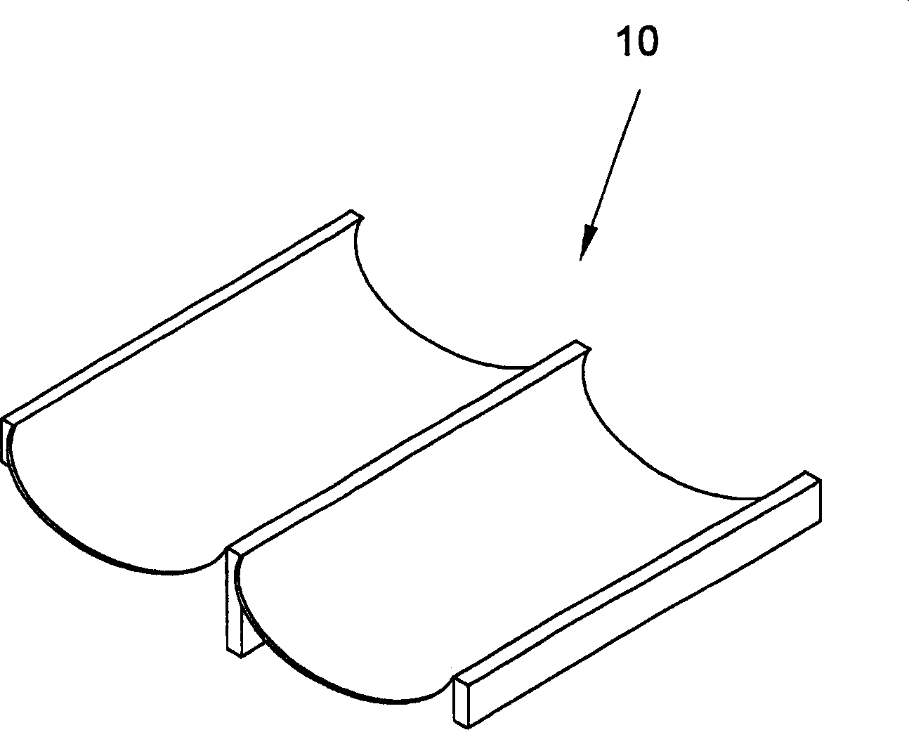
[0021] In addition, each work station 2 of the textile machine 1 includes: a winding unit 6 for accommodating the bobbin and forming the twisted bobbin 8 to be produced; A container 9 for containing the twist bobbins 8 formed at each workstation 2 . The receiving device 9 can also be formed as image 3 The reservoir 10 shown is adapted to the size of the twist bobbins 8 .

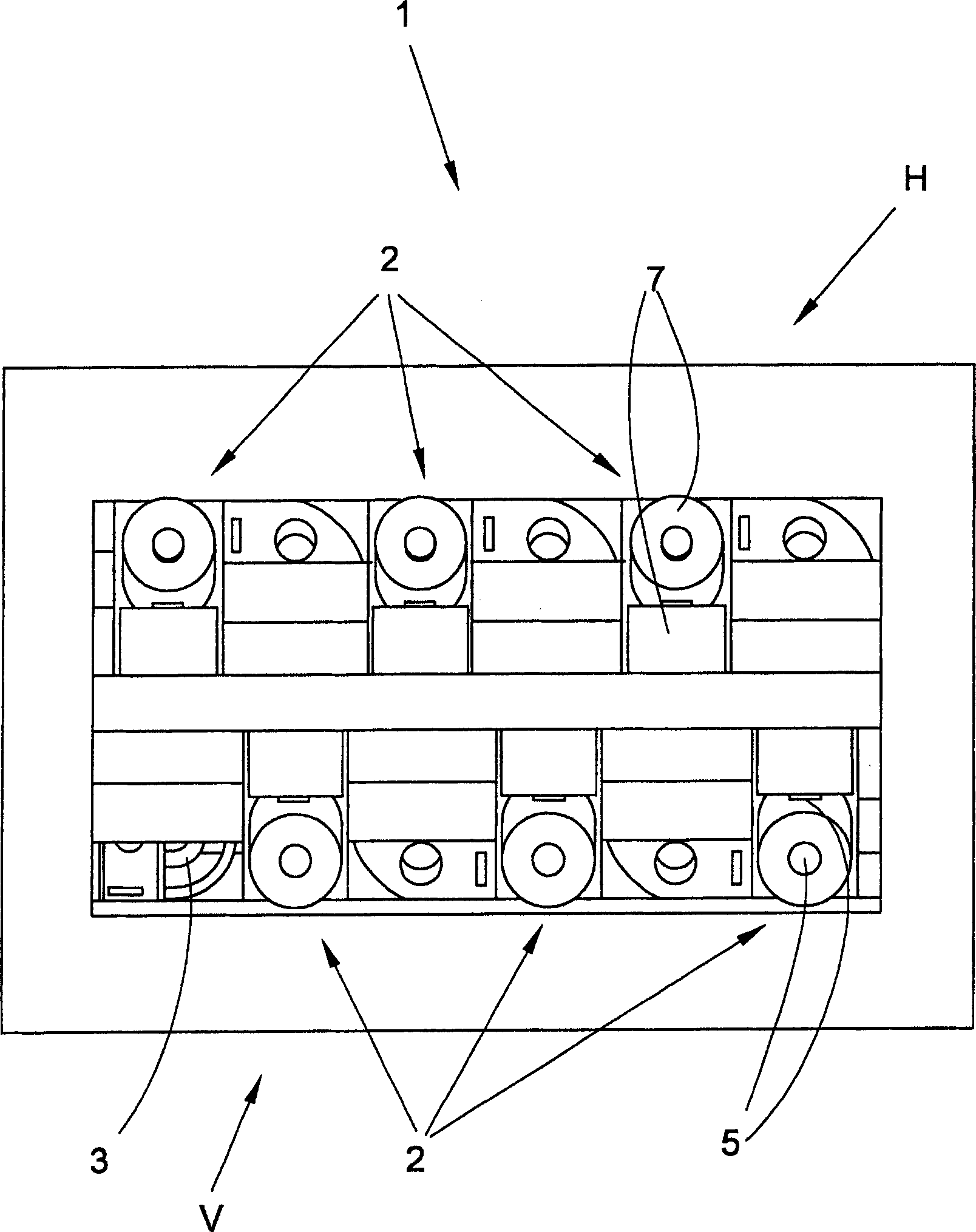
[0022] figure 2 The view of represents a partial view of the spinning machine 1 according to the invention. The arrangement according to the invention of the workstations 2 with their respective...


PUM


Abstract

The invention provides a fiber machine for producing twisted yarn packagetextile. This fiber machine 1 is equipped with many working parts 2 arranged on both sides of the fiber machine in a longitudinal direction of the machine, wherein the working parts 2 each have a spindle 3, a winding unit 6 mounted on the fiber machine above the spindle 3, and a package creel 4, and the spindle 3 and the package creel 4 are arranged in parallel in each of the working parts 2.

Description

technical field [0001] The invention relates to a textile machine for producing twisted yarn bobbins according to the preamble of claim 1 . Background technique [0002] A textile machine according to the preamble of claim 1 is known from EP 1 528 128 A2. Therein, a textile machine is described which is provided with workstations on both sides in the longitudinal direction of the machine, which workstations each comprise a spindle and a creel. In order to achieve the highest possible productivity of the textile machine, the spindles of the individual workstations are arranged adjacent to one another on both sides of the machine frame and opposite one another in the lower part of the textile machine. The associated creels of the individual workstations are arranged above the individual spindles on the upper side of the textile machine on the frame. The creel is pivoted about a horizontal axis towards the operative side for assembling the feed cylinder. [0003] Furthermore...

Claims


Application Information

Patent Timeline
Patent Type & Authority Applications(China)
IPC IPC(8): D01H1/14
CPCB65H67/066B65H67/0411B65H2701/31D01H1/18D01H9/006
Inventor 格哈德·韦尔梅斯特汉斯·居热莫
Owner SAURER GMBH & CO KG
Why Eureka
Try Eureka