Construction element for heat insulation

A technology of structural elements, structural components, applied in the field of structural elements for thermal insulation, to achieve optimal orientation

Inactive Publication Date: 2007-02-21
SCHOCK BAUTEILE GMBH
View PDF0 Cites 3 Cited by
  • Summary
  • Abstract
  • Description
  • Claims
  • Application Information

AI Technical Summary

Problems solved by technology

It is clear that the known structural elements for thermal insulation with an insulation thickness of only 8 cm are not suitable for the requirements of passive houses, so that protruding external parts such as in particular balconies are either completely eliminated, or the protruding external parts are deliberately reduced. Compromise for thermal insulation in the zone

Method used


Image

  • Construction element for heat insulation
  • Construction element for heat insulation

Examples


Embodiment Construction

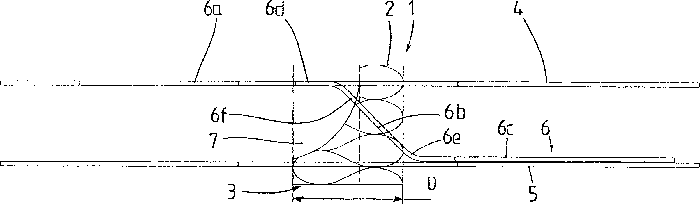
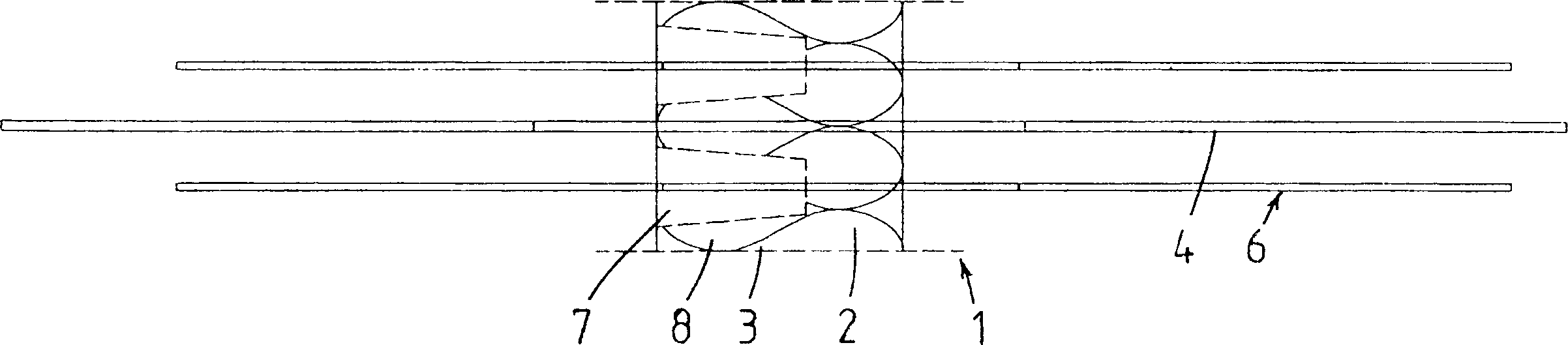
[0012] figure 1 with figure 2 The structural element 1 for thermal insulation shown in includes an insulator 2 with integral protrusions 3 made of the same insulator material and a number of reinforcing bars traversing the insulator - i.e. in the upper Tie bars 4 extending horizontally in the insulation area, compression bars 5 and shear bars 6 extending horizontally in the lower insulation area, wherein the shear bars are in vertical planes parallel to each other inside the insulation has a distinctly inclined distribution section 6b and is bent in areas 6d, 6e at the upper distribution section 6a and at the lower distribution section 6c for connection to two adjoining concrete structural parts, so that said distribution section Protruding horizontally from the insulation at different heights in the vertical plane, the upper distribution section 6 a is assigned to the supporting structural part and the lower distribution section 6 c is assigned to the supported structural p...


PUM


Abstract

A construction element for heat insulation between two construction parts, in particular between a building part and a protruding exterior part, is provided, and includes an insulating body ( 2 ) to be arranged between the two construction parts with reinforcement elements ( 4, 5, 6 ) that can cross it and that can be connected to the two construction parts, with at least shear force rods ( 6 ) being provided as reinforcement elements. The construction element is here adjusted for the installation in passively energy conserving houses such that the insulating body is provided with a protrusion ( 3 ), which includes open recesses ( 7 ) for the upper exit sections ( 6 f) of the shear force rods ( 6 ) that extend out of the insulating body, and extend in the direction of the supporting building part to the area of the horizontally protruding shear force rod sections ( 6a ) so that it laterally overlaps the bent shear force rod sections ( 6d ) in their entirety.

Description

technical field [0001] The invention relates to a construction element for thermal insulation between two structural parts, in particular between a building part and a protruding exterior part, comprising a thermal insulation to be arranged between said two structural parts , the insulation has a reinforcement element that traverses the insulation and can be connected to the two structural parts, wherein at least shear bars are provided as reinforcement elements, and these shear bars are vertically parallel to each other inside the insulation Extends significantly obliquely in the plane and is supported for connection to the two structural parts at the upper distribution section of the shear bar assigned to the supporting structural part and at the assigned part of the shear bar The structural member is bent at the lower distribution section so that said distribution section protrudes horizontally from the insulation at different heights in said vertical plane. Background te...

Claims


Application Information

Patent Timeline
Patent Type & Authority Applications(China)
IPC IPC(8): E04B1/78
CPCY02B30/94E04B1/0038Y02A30/00Y02B30/90
Inventor H·弗里特施
Owner SCHOCK BAUTEILE GMBH
Why Eureka
Try Eureka