Electronical expansion valve in use for refrigeration system

An electronic expansion valve, refrigeration system technology, applied in the direction of lift valve, valve details, valve device, etc., can solve the problems of reducing valve stability and reliability, increasing processing difficulty and cost, increasing expansion valve leakage, etc. The effect of improving reliability, simple structure and stable friction resistance

Inactive Publication Date: 2007-02-21
ZHEJIANG DUNAN ARTIFICIAL ENVIRONMENT
View PDF0 Cites 17 Cited by
  • Summary
  • Abstract
  • Description
  • Claims
  • Application Information

AI Technical Summary

Problems solved by technology

With this structure, there are the following defects: 1) Since the valve needle also moves up and down while rotating, in order to control the opening reference point and range of the valve, it is necessary to set up a fixed-angle screw positioning control mechanism. After using this control mechanism, the expansion valve The structure is complex and the volume increases, which increases the processing difficulty and cost; 2) Because the rotor moves up and down, the driving torque of the stepping motor changes periodically with the up and down of the rotor, which reduces the stability and reliability of the valve.
With this structure, there are the following defects: 1) Since the valve core cannot be self-locked in the process of rotation, in order to maintain the flow rate of the expansion valve, the stator coil of the valve must be energized all the time, which reduces the stability of the valve and increases its performance. 2) Due to the relative rotation between the valve core and the valve body, there needs to be a certain gap between the two, which will increase the internal leakage of the expansion valve, making the valve unable to be used in a one-to-many refrigeration system

Method used


Image

  • Electronical expansion valve in use for refrigeration system
  • Electronical expansion valve in use for refrigeration system
  • Electronical expansion valve in use for refrigeration system

Examples


Embodiment 1

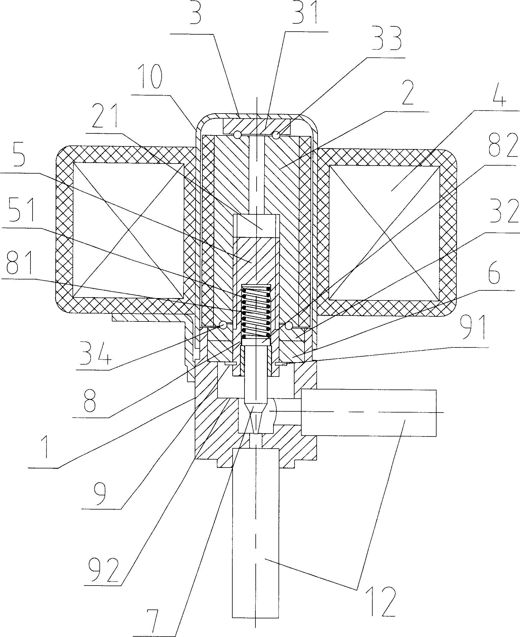
[0044] Embodiment one, such as Figures 1 to 3 As shown, an electronic expansion valve used in a refrigeration system includes a valve body 1, a rotor 2, a positioning device 3, a coil 4, a mandrel screw 5, an anti-rotation part 6, a valve needle 7, an adjustment device 8, and a limit device 9. A sealing sleeve 10, a coil positioning bracket 11 and an inlet and outlet connecting pipe 12.

[0045] Among them, the sealing sleeve 10 is sleeved and welded on the valve body 1; the coil fixing frame 11 is fixed on the valve body 1; the coil 4 is set outside the sealing sleeve 10 and fixed on the coil fixing frame 11; the valve body 1 corresponds to the coil The rotor 2 is installed at 4 places; the positioning device 3 includes upper and lower bearing supports 31, 32 and upper and lower bearing supports 33, 34, the upper and lower bearing supports 31, 32 are respectively fixed in the valve body 1, and the upper bearing supports 33 Installed in the upper bearing support block 31 an...

Embodiment 2

[0048] Embodiment two, such as Figure 4 As shown, an electronic expansion valve used in a refrigeration system is different from Embodiment 1 in that only the lower bearing-type support 32 and the lower bearing-type support 34 are used to realize the positioning device 3, and the upper bearing-type support is not required. 31 and the upper bearing support 33, the lower bearing support 32 is fixed in the valve body 1, the lower bearing support 34 is installed in the lower bearing support 32, and cooperates with the lower end of the rotor 2, the lower bearing support 34 is Rolling bearing type support. work process:

[0049] The coil 4 is connected with direct current according to a certain phase sequence, and a rotating magnetic field is generated around the coil 4; the rotor 2 is affected by the rotating magnetic field, and under the limitation of the upper bearing support 33, it cannot perform lifting motion, but only rotates; the rotor 2 The rotation is transmitted to the...

Embodiment 3

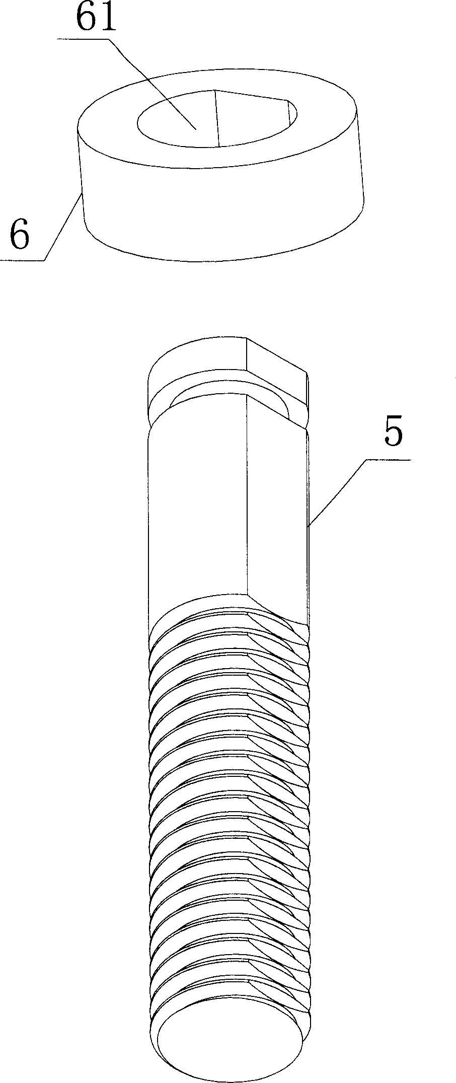
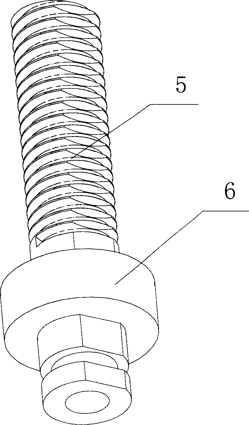
[0052] Embodiment three, such as Figure 5 As shown, the difference from Embodiment 1 is that one end of the mandrel screw 5 is placed in the cavity at the lower part of the valve body 1, and is threadedly fitted with the valve body 1; the anti-rotation part 6 is fixed in the rotor 2 to prevent The rotating part 6 can be fixed in the rotor 2 through interference fit or welding, and the other end of the mandrel screw 5 is installed in the anti-rotation part 6, and the rotor 2 drives the mandrel screw 5 to rotate and lift through the anti-rotation part 6 The limiting device 9 is set in the valve body 1 to limit the range of the mandrel screw 5 for lifting movement; the upper end of the valve needle 7 is installed in the second cavity 51 at the bottom of the mandrel screw 5 . Correspondingly, the limit device 9 includes an upper limit device 91 and a lower limit device 92. The upper limit device 91 is the top wall of the valve body 1. When the spindle screw 5 moves upward to the ...


PUM


Abstract

An expansion valve used on refrigeration system is prepared as sheathing coil on valve body, erecting rotator in valve body and corresponding it to said coil, setting the positioning unit in valve body and coordinating it with said rotator, setting lift mechanism in valve body and coordinating it to said rotator, setting space unit in valve body and using it to limit lifting range of said lift mechanism, erecting top end of needle valve in the second cavity at bottom of lift mechanism.

Description

technical field [0001] The invention relates to an electronic expansion valve used in a refrigeration system, in particular to an electronic expansion valve used in a one-to-multiple or variable-frequency variable-capacity refrigeration system. Background technique [0002] The electronic expansion valve mainly adjusts the heat output per unit time of the refrigeration system automatically by adjusting the circuit flow rate of the refrigerant in the refrigeration system. [0003] At present, there is an electronic expansion valve driven by a stepping motor. The valve needle is integrated with the rotor of the motor. The threaded sub-rotor drives the valve needle to move up and down while rotating, thereby changing the flow area of ​​the valve port. With this structure, there are the following defects: 1) Since the valve needle also moves up and down while rotating, in order to control the opening reference point and range of the valve, it is necessary to set up a fixed-angle...

Claims


Application Information

Patent Timeline
IPC IPC(8): F16K1/00F16K31/04
CPCF25B2341/065F16K31/04F25B41/062Y02B30/72Y02B30/70F25B41/34F25B41/35
Inventor 冯忠波何国平蔡培裕王冠军
Owner ZHEJIANG DUNAN ARTIFICIAL ENVIRONMENT
Why Eureka
Try Eureka