Wall flow-less jetting cooling tower

A cooling water tower and jet technology, applied in water shower coolers, direct contact heat exchangers, heat exchanger types, etc., can solve problems such as affecting the flow state of the mainstream field, unable to cure wall flow, affecting air volume inhalation, etc. Achieve the effect of ensuring the amount of air entering the tower, improving the flow field in the tower, and eliminating the phenomenon of wall flow

Inactive Publication Date: 2007-02-21
SHANGHAI JIAO TONG UNIV
View PDF0 Cites 4 Cited by
  • Summary
  • Abstract
  • Description
  • Claims
  • Application Information

AI Technical Summary

Problems solved by technology

In the existing technology, there is another technology that installs intermittent bumps on the bottom of the diffuser to make the water curtain splash, but it will affect the flow state of the main flow field, affect the air intake, and lead to different degrees of decline in cooling effect. wall flow

Method used


Image

  • Wall flow-less jetting cooling tower
  • Wall flow-less jetting cooling tower
  • Wall flow-less jetting cooling tower

Examples


Embodiment Construction

[0019] The technical solution of the present invention will be further described below in conjunction with the accompanying drawings.

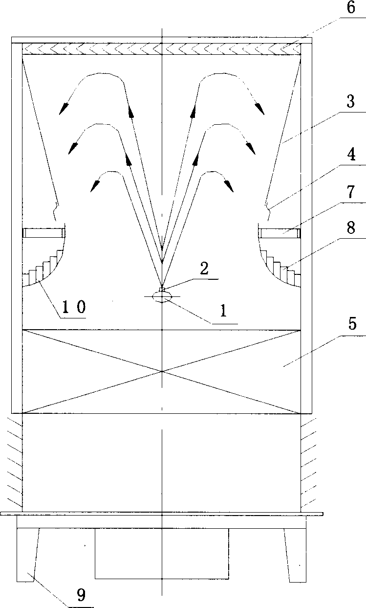
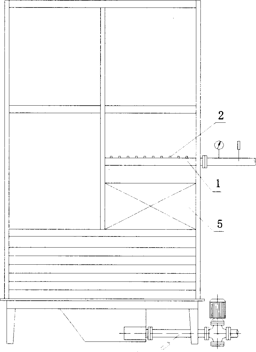
[0020] The structure of the wallless jet cooling water tower provided by the invention is as follows: figure 1 As shown, it includes a nozzle 1, a nozzle 2, a diffuser section 3, a deflector 4, a packing layer 5, a water eliminator 6, a sump 7, a compartment 8, a tower 9, and an arc deflector 10. Nozzles 1 are arranged in the middle of the cooling water tower, nozzles 2 are evenly arranged on the nozzles 1 at certain intervals, and a packing layer 5 is arranged below the nozzles 1 . There is a horizontal slit on the wall above the minimum cross-section of the lower end of the water tower diffuser section 3, and an outwardly protruding deflector 4 is installed on the outer side of the lower edge of the wall of the diffuser section 3, and the protruding distance is according to the cooling tower shower. Depends on the density of water. Below t...


PUM


Abstract

A cooling water tower of injection and wall stream free type is featured as opening horizontal seam on wall surface of pressure expansion section at cooling rower and setting stream guide plate at bottom edge of said wall surface for leading water from said wall surface to water collection tank, dropping water out from holes of said tank to separation chambers of arc shaped stream guide plate under said tank, flowing water out in uniform speed from holes at bottom of said separation chamber for entering water into packing layer uniformly.

Description

technical field [0001] The invention relates to a cooling water tower without wall-flow injection, which can effectively eliminate the wall flow at the bottom of the diffuser, increase the amount of air entering the tower, and further improve the cooling effect of water. It belongs to the technical field of fluid engineering. Background technique [0002] Among the spray cooling towers, many vertically arranged cooling towers use nozzles installed in front of the throat of the tapering and expanding pipe to spray water at high speed from bottom to top, forming a low-pressure area at the throat of the tapering and expanding pipe. The outside air flows into the cooling tower under the action of atmospheric pressure, mixes with the sprayed water, evaporates part of the water on the outer surface of the water droplet, and performs heat and mass exchange, thereby reducing the temperature of the water droplet, and the evaporated water becomes water vapor After that, it is dischar...

Claims


Application Information

Patent Timeline
Patent Type & Authority Applications(China)
IPC IPC(8): F28F25/08
Inventor 任世瑶
Owner SHANGHAI JIAO TONG UNIV
Why Eureka
Try Eureka