Rotation angle sensing device

A sensing device, angle sensing technology, applied in engine control, machine/engine, electrical control, etc., can solve the problems of complex manufacturing process and difficult to sense angle error.

Active Publication Date: 2007-02-28
DENSO CORP
View PDF3 Cites 15 Cited by
  • Summary
  • Abstract
  • Description
  • Claims
  • Application Information

AI Technical Summary

Problems solved by technology

Therefore, it is difficult to sense the angle error with high precision
Also, the device must be prepared for a theoretical time for sensing the angular error, complicating the manufacturing process of the device

Method used


Image

  • Rotation angle sensing device
  • Rotation angle sensing device
  • Rotation angle sensing device

Examples


Embodiment Construction

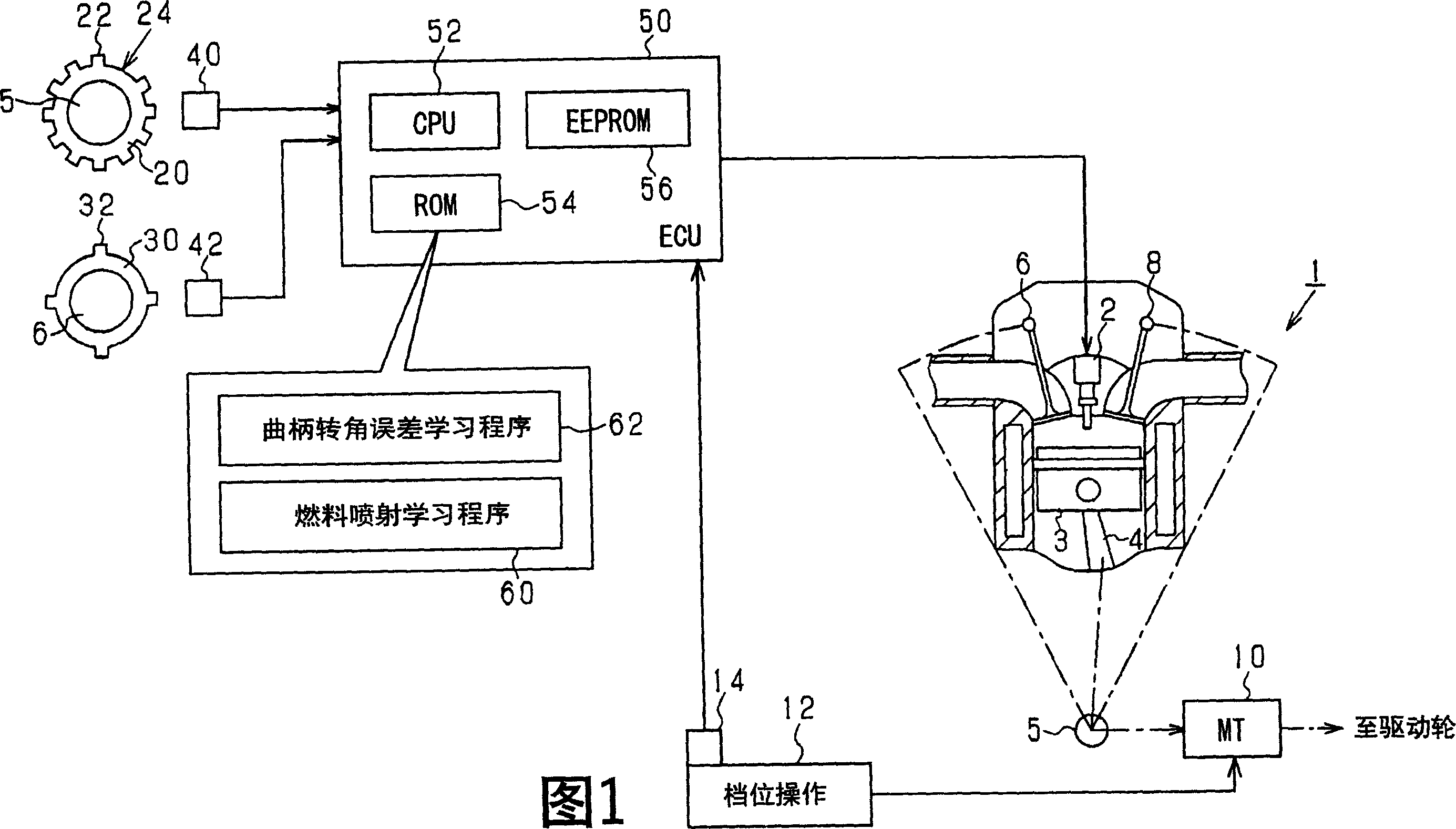
[0046] Referring to FIG. 1 , there is shown a rotation angle sensing device according to a first exemplary embodiment of the present invention, which is applied to a rotation angle sensing device of a diesel engine mounted on a manual transmission vehicle. The diesel engine 1 shown in FIG. 1 is a multi-cylinder (four cylinders in this embodiment) internal combustion engine. An actuator such as a fuel injection valve 2 is provided on each cylinder. The piston 3 of each cylinder is connected with the crankshaft 5 through the connecting rod 4 . The crankshaft 5 is mechanically connected to the camshafts 6, 8. Each camshaft 6, 8 makes one revolution while the crankshaft 5 makes two revolutions. The diesel engine 1 is a four-stroke engine. The crankshaft 5 may be connected to the drive wheels through a manual transmission (MT). The gear position operation of the gear operating section 12 is completed by the user. The gear position of the MT 10 is changed by the operation of th...


PUM


Abstract

A rotation angle sensing device calculates an average value of calculation values of time necessary for rotation of each one of sections provided by equally dividing one rotation of a crankshaft. The device calculates an average value of the average values of the entire sections to calculate an entire section average value. The device calculates ratios of the average values of the respective sections to the entire section average value. The device eliminates an influence of rotation fluctuation of the crankshaft from the ratios by using reference ratios, which are calculated as ratios of the average values of the respective sections to the entire section average value in the case where there is no structural error. Thus, the device calculates learning values for compensating for the structural error.

Description

technical field [0001] The present invention relates to a rotation angle sensing device for receiving an output of a crank angle sensor that senses a plurality of sensed portions that rotate synchronously with a crankshaft of an internal combustion engine to detect a crankshaft rotation angle. Background technique [0002] A known rotation angle sensing device of this type senses an output shaft ( angle of rotation of the crankshaft). Often, the spacing between actual teeth has structural errors. This structural error produces an error in sensing the crankshaft rotation angle. [0003] Thus, for example, a device described in JP-A-H11-247707 senses the time required for a segment defined by two teeth to rotate and compares the sensed time with a theoretical time to sense two Angle error between teeth. One rotation angle of the crankshaft is divided into a plurality of segments according to teeth, and a theoretical time is defined for each divided segment. With this devi...

Claims


Application Information

Patent Timeline
Patent Type & Authority Applications(China)
IPC IPC(8): F02D45/00
CPCY02T10/40
Inventor 石塚康治中田谦一郎
Owner DENSO CORP
Why Eureka
Try Eureka