Magnetoresistive effect element, magnetic head, magnetic storage device and magnetic memory device

A magnetoresistance effect element and magnetoresistance effect technology, which are used in the manufacture of magnetic flux sensitive magnetic heads, information storage, electrical components, etc., and can solve the problems of difficult rotation of magnetization, reduction of substantial changes in magnetoresistance, and decline in output of magnetoresistance elements.

Inactive Publication Date: 2007-02-28
FUJITSU LTD
View PDF4 Cites 2 Cited by
  • Summary
  • Abstract
  • Description
  • Claims
  • Application Information

AI Technical Summary

Problems solved by technology

Therefore, the substantial amount of change in magnetoresistance is reduced, resulting in a decrease in the output of the magnetoresistive element
In addition, if the coercive force is too large, the magnetization of the free magnetization layer generated by the signal magnetic field is difficult to rotate, resulting in difficulty in obtaining output

Method used


Image

  • Magnetoresistive effect element, magnetic head, magnetic storage device and magnetic memory device
  • Magnetoresistive effect element, magnetic head, magnetic storage device and magnetic memory device
  • Magnetoresistive effect element, magnetic head, magnetic storage device and magnetic memory device

Examples


no. 1 approach

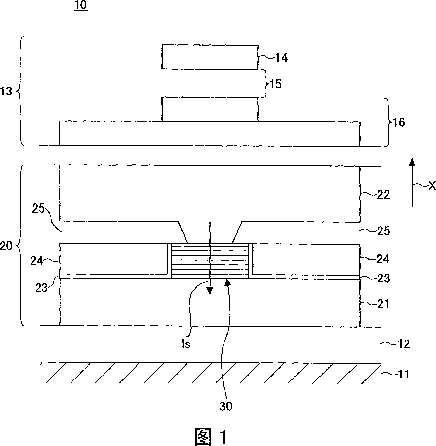
[0043] A composite type magnetic head having the magnetoresistive effect element and the inductive recording element according to the first embodiment of the present invention will be described below. FIG. 1 is a schematic diagram showing a part of the composite type magnetic head. In FIG. 1, arrow X indicates the moving direction of the magnetic recording medium facing the magnetoresistive effect element.

[0044] 1, the composite magnetic head 10 includes: a planar ceramic substrate 11, which is made of Al 2 O 3 -TiC is formed and used as a head slider; a magnetoresistance effect element 20 is formed on the ceramic substrate 11 ; and an inductive recording element 13 is formed on the magnetoresistance effect element 20 .

[0045] The inductive recording element 13 includes: an upper magnetic pole 14, facing the magnetic recording medium and having a width corresponding to the track width of the magnetic recording medium; a recording gap layer 15; a lower magnetic pole 16, ...

Embodiment 1

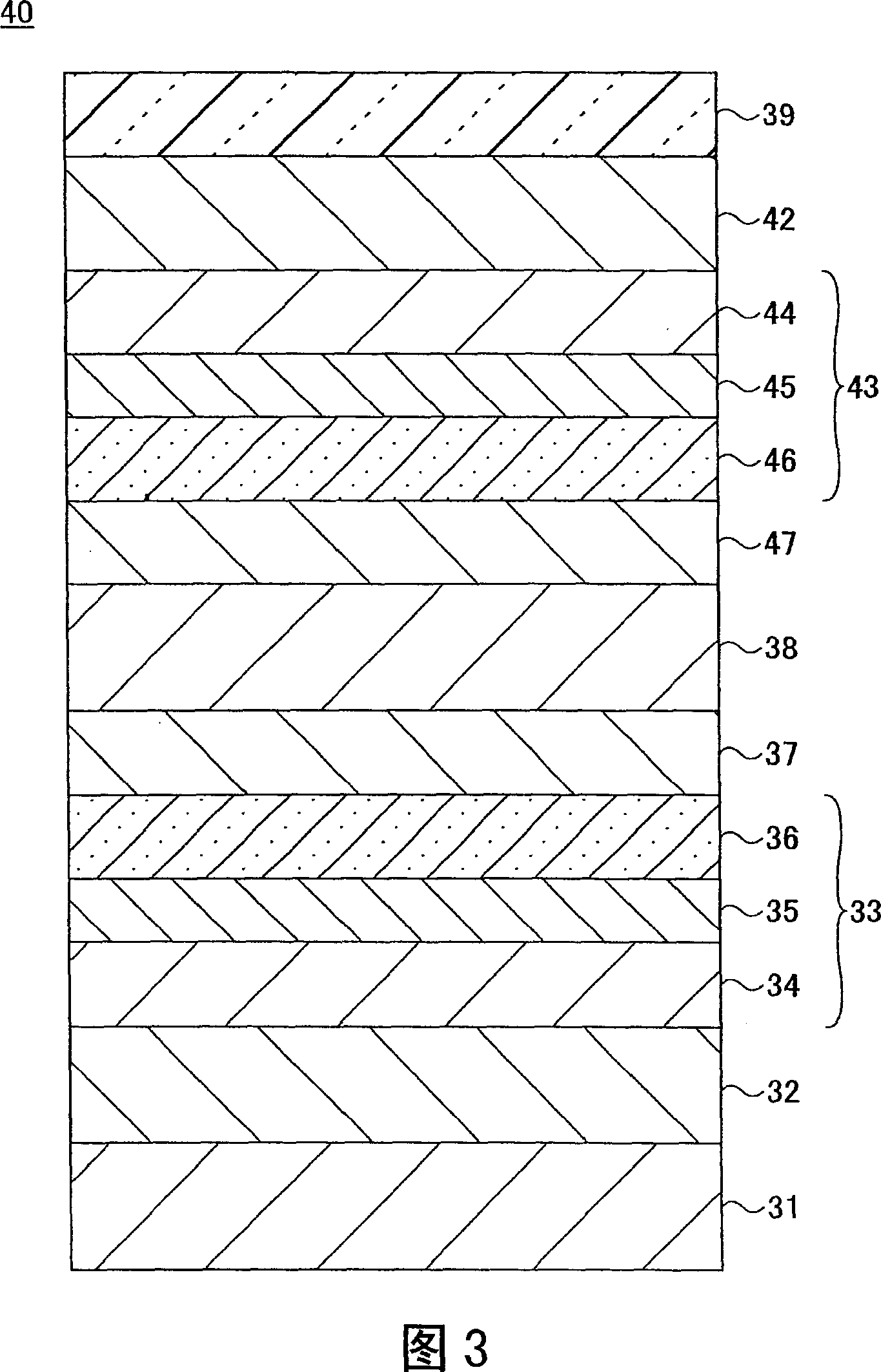
[0098] In Example 1, a magnetoresistance effect element having the GMR film structure of the second example shown in FIG. 3 was fabricated.

[0099] 7 is a graph showing the composition, coercive force, and magnetoresistance variation ΔRA of the free magnetization layer and the upper and lower second fixed magnetization layers in Embodiment 1. FIG.

[0100] Referring to FIG. 7, CoFeAl compositions for the lower second fixed magnetization layer, the free magnetization layer, and the upper second fixed magnetization layer in samples No. 1 to No. 27 were changed. The sample of Example 1 was prepared by the following method.

[0101] A laminated film of Cu (250 nm) / NiFe (50 nm) was formed as a lower electrode on a silicon substrate on which a thermally oxidized film was formed. Then, without heating the substrate, in an ultra-vacuum atmosphere (vacuum degree: equal to or lower than 2×10 -6 In Pa) each layer from the base layer to the protective layer of the lower laminate was fo...

Embodiment 2

[0127] In Example 2, a magnetoresistive effect element having the GMR film structure of the fifth example according to the first embodiment shown in FIG. 6 was fabricated. In this embodiment, the composition of the free magnetization layer is fixed to Co 50 Fe 20 Al 30 , while changing the CoFeAl composition of the lower second fixed magnetization layer and the upper second fixed magnetization layer to form the magnetoresistive effect elements of the samples Nos. 31 to 37. The composition range of samples Nos. 31 to 37 is the range CHIDC in FIG. 8 . The range CHIDC is defined by a plurality of straight lines successively connecting the points C, H, I, D and C, wherein the point H is (40, 30, 30) and the point I is (50, 30, 20). The coordinates of the components are represented by (Co content, Fe content, Al content). Note that the lower second pinned magnetization layer and the upper second pinned magnetization layer in the same sample are set to have the same composition....


PUM

PropertyMeasurementUnit
thicknessaaaaaaaaaa

Abstract

The present invention relates to a magnetoresistive effect element, magnetic head, magnetic storage device and magnetic memory device. A magnetoresistive effect element of a CPP type includes a fixed magnetization layer, a non-magnetic layer and a free magnetization layer formed of CoFeAl. The CoFeAl has a composition falling within a range defined by straight lines connecting points A, B, C, D, E, F and A, in that order, in a ternary composition diagram. The point A is (55, 10, 35), the point B is (50, 15, 35), the point C is (50, 20, 30), the point D is (55, 25, 20), the point E is (60, 25, 15), and the point F is (70, 15, 15), where coordinates of the composition of each point is represented by (Co content, Fe content, Al content). Each content is expressed by atomic percent.

Description

technical field [0001] The present invention relates to a magnetoresistance effect element for reproducing information in a magnetic storage device, and in particular to a magnetoresistance effect element having a CPP (current direction perpendicular to the plane) structure. A sense current flows along the stacking direction of the film stacks constituting the magnetoresistive effect element. Background technique [0002] In recent years, the magnetoresistive effect element is used as a reproducing element for reproducing information recorded on a magnetic recording medium, a magnetic head for magnetic storage. The magnetoresistive effect element reproduces information recorded on a magnetic recording medium using the magnetoresistive effect, which converts a change in the direction of a signal magnetic field leaked from the magnetic recording medium into a change in resistance. [0003] As magnetic memory devices have progressed in high recording density, magnetic heads ha...

Claims


Application Information

Patent Timeline
Patent Type & Authority Applications(China)
IPC IPC(8): H01L43/08G11B5/39G11B5/00H01F10/32
CPCG01R33/093G11B5/3906H01L43/10H01F10/3254B82Y25/00H01F10/3263H01L27/228H01F10/16H01F10/3272Y10T428/21H10B61/22H10N50/85H10N50/10
Inventor 城后新大岛弘敬长坂惠一
Owner FUJITSU LTD
Why Eureka
Try Eureka