
Postponing circuit with high electrical-magnetic compatibility

A technology of electromagnetic compatibility and delay circuit, applied in electrical components, pulse processing, single output arrangement, etc., can solve problems such as weak driving ability, failure of subsequent functional circuits to operate normally, circuit malfunction, etc.

Inactive Publication Date: 2007-02-28
SINO WEALTH ELECTRONICS
View PDF0 Cites 0 Cited by
  • Summary
  • Abstract
  • Description
  • Claims
  • Application Information

AI Technical Summary

Problems solved by technology

Therefore, when the noise from the power supply is greater than 0.5 times the power supply voltage, an error will occur in the output signal, which will cause the problem that the subsequent functional circuit cannot operate normally.
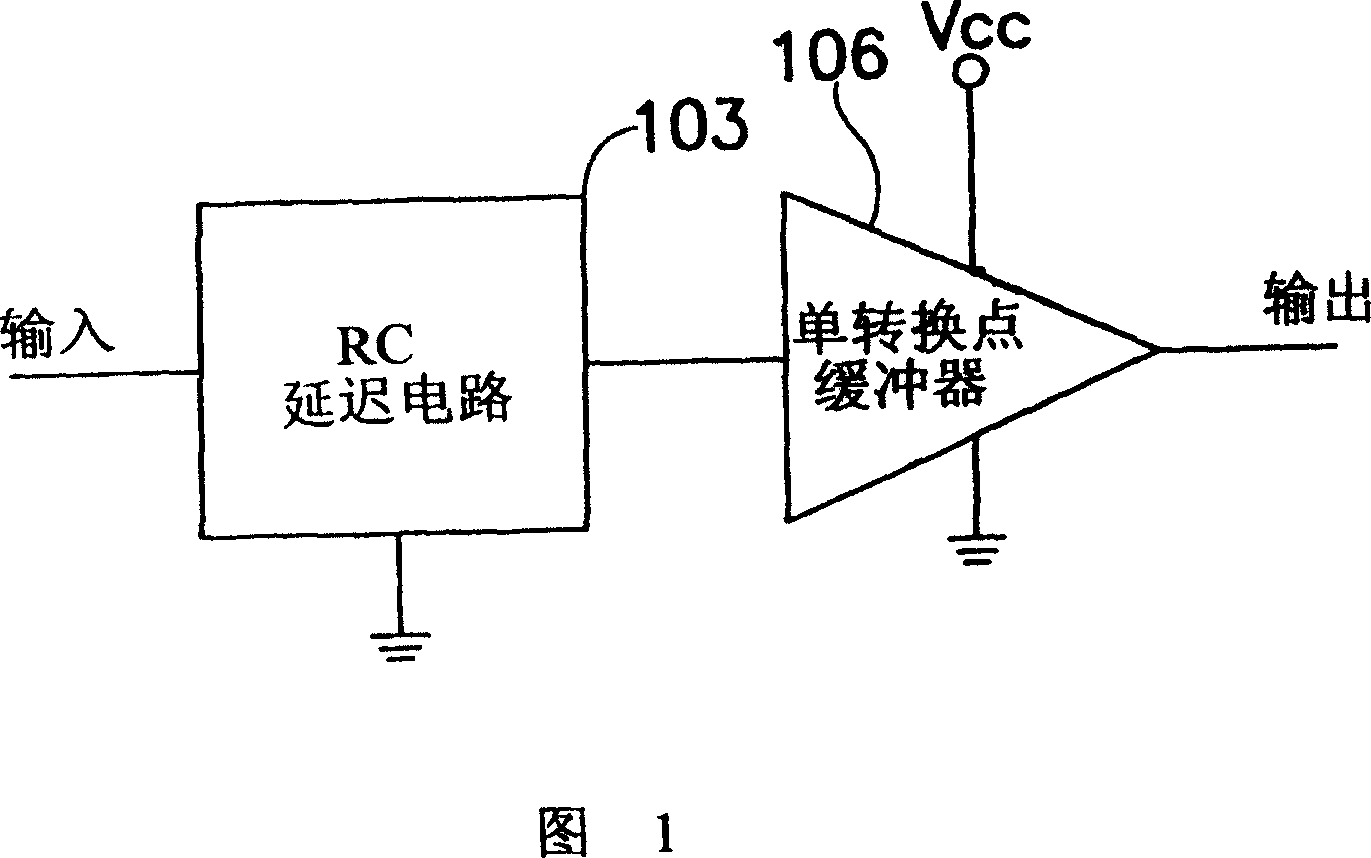
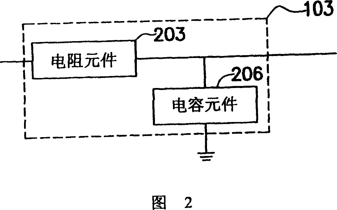
[0006] In the known technology, the resistance component 203 is easily disturbed by noise due to its weak driving ability, and the capacitor component 206 used is easy to induce noise from the power supply or the circuit substrate (CircuitSubstrate), etc.
Based on the above, it can be seen that the delay circuit in the known technology is a circuit with low electromagnetic compatibility, which is easily interfered by other circuits. Once a delay circuit with low electromagnetic compatibility is used, it will be affected by noise and produce an erroneous output signal containing glitches. It will lead to malfunction of subsequent circuits or other components, and even more serious physical damage will occur

Method used


Image

  • Postponing circuit with high electrical-magnetic compatibility
  • Postponing circuit with high electrical-magnetic compatibility
  • Postponing circuit with high electrical-magnetic compatibility

Examples


Embodiment Construction

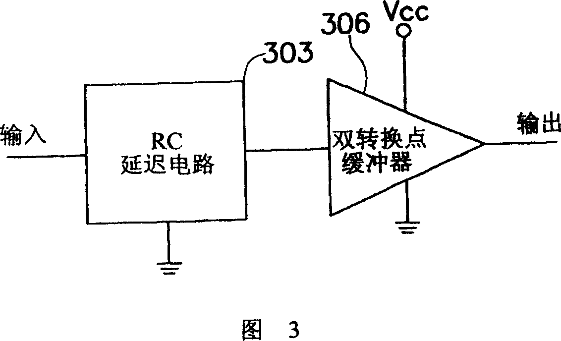
[0037] Please refer to FIG. 3 , which shows a schematic block diagram of a delay circuit according to a first preferred embodiment of the present invention. This delay circuit includes an RC delay circuit 303 and a double conversion point buffer 306, wherein the internal device of the RC delay circuit 303 is the same as the block diagram of the RC delay circuit shown in FIG. The composed RC delay circuit 303. Its action is that the input signal will be transformed into a delayed signal with a delay time through the RC delay circuit 303 composed of the resistance component 203 and the capacitor component 206, and the delay time of the delay signal is the RC time constant.

[0038]The next double switching point buffer 306 provides two level voltages, which can enhance the tolerance to noise. In a preferred embodiment of the present invention, the double switching point buffer 306 can be a Schmitt Trigger Circuit (Schmitt Trigger Circuit). Those skilled in the art will know tha...


PUM


Abstract

The invention relates to a delay circuit with high electromagnetic compatibility. Wherein, said circuit uses dual-capacitor RC delay circuit to replace the RC delay circuit, to disperse the noise strength; and uses dual-conversion point buffer to replace single-conversion point buffer, while the dual-conversion point buffer can provide two reference voltages to improve the output signal quality and overcome noise.

Description

technical field [0001] The present invention relates to a delay circuit, and in particular to a delay circuit with high electromagnetic compatibility. Background technique [0002] Due to the advancement of semiconductor process technology, the technology of large scale integration (LSI) has rapidly advanced to the technology of very large scale integration (VLSI) or ultra large scale integration (Ultra Large Scale Integration, ULSI) technology, which means that the number of integrated components that can be tolerated on a single chip is increasing. Due to the increasing density per unit area of ​​integrated components and the increasing operating frequency of integrated components, the problem of mutual electromagnetic interference (EMI) between circuits is becoming more and more serious. Because electromagnetic interference can cause harm to the human body, all countries in the world have set clear limits on the electromagnetic interference generated by electronic produc...

Claims


Application Information

Patent Timeline
IPC IPC(8): H03K5/13H03K5/1252H03K5/14
Inventor 朱秉濬
Owner SINO WEALTH ELECTRONICS
Learn More