Display unit

A display unit, display panel technology, applied in the direction of static indicators, instruments, etc.

Inactive Publication Date: 2007-02-28
KONINKLIJKE PHILIPS ELECTRONICS NV
View PDF2 Cites 9 Cited by
  • Summary
  • Abstract
  • Description
  • Claims
  • Application Information

AI Technical Summary

Problems solved by technology

[0008] A disadvantage of existing display units, among others, is that, due to stillness, relatively large gradients are included within the image

Method used


Image

  • Display unit
  • Display unit
  • Display unit

Examples


Embodiment Construction

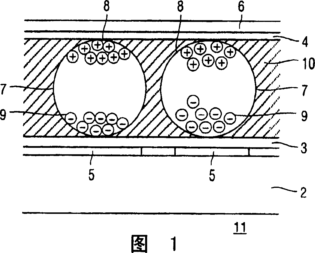
[0037] The bistable pixel 11 of the display unit shown in FIG. 1 (cross-sectional view) comprises a base plate 2 (such as plastic or glass), an electrophoretic film (laminated on the base plate 2) with electronic ink, wherein the electronic ink is present in a glue layer 3 and Between the common electrodes 4. Transparent pixel electrodes 5 are provided on the glue layer 3 . Electronic ink includes many microbodies 7 with a diameter of about 10 to 50 microns. Each microbody 7 comprises positively charged white particles 8 and negatively charged black particles 9 suspended in a liquid 10 . When a positive voltage is applied to the pixel electrode 5, the white particles 8 move towards the side of the microbody 7 directed to the common electrode 4, and the pixel can be seen by the observer. At the same time, the black particles 9 move to the opposite side of the micro bodies 7 so that they are not seen by the observer. By applying a negative voltage to the pixel electrode 5, th...


PUM


Abstract

Display units (1) comprising pixels arranged in rows and columns coupled via transistors (12) to row (41, 45, 49) and column (31, 32, 39) electrodes show a relatively large gradient in the image. By introducing means (30, 40) for reducing a voltage difference resulting from a voltage jump on a predefined line, which voltage jump arrives via a capacitance (13, 14), this gradient is reduced. The capacitance (13, 14) may comprise a storage capacitor (13), with the predefined line being a neighbouring row electrode (41, 45, 49) or a separate storage line (25). The capacitance (13, 14) may also comprise a parasitic capacitor (14) of the transistor (12), with the predefined line corresponding with the row electrode (41, 45, 49) in the same row. The means (30, 40) comprise line driving circuitry (40) and data driving circuitry (30) for supplying a data signal to pixels (11). The means (30, 40) may also comprise line driving circuitry (40) for driving at a reduced amplitude and may comprise storage line driving circuitry for driving the storage line (25).

Description

technical field [0001] The invention relates to a display unit, a display device comprising the display unit, a method for driving the display unit and a processor program product for driving the display unit. [0002] Examples of this type of display device include: monitors, laptop computers, personal digital assistants (PDAs), mobile phones, and electronic books, electronic newspapers, and electronic magazines. Background technique [0003] A known display unit is known from US patent US2002 / 0005832A1. The above patent application discloses an electrophoretic display comprising pixels arranged in rows and columns. Each pixel is connected to a common or counter electrode and via the pixel electrode to the drain of a transistor whose source is connected to a column or data electrode and whose gate is connected to a row or select electrode. The above-described structure of pixels, transistors, and row and column electrodes together form an active matrix. A row driver (sel...

Claims


Application Information

Patent Timeline
Patent Type & Authority Applications(China)
IPC IPC(8): G09G3/34
CPCG09G2310/0251G09G2320/0233G09G2310/0205G09G2300/08G09G2310/068G09G2300/0876G09G3/344
Inventor S·J·范德霍弗H·E·A·胡伊特马L·W·G·斯托夫梅尔L·M·海格
Owner KONINKLIJKE PHILIPS ELECTRONICS NV
Why Eureka
Try Eureka