Waterproof case for in-vehicle camera

A technology for vehicle-mounted cameras and waterproof boxes, which is applied to vehicle parts, televisions, electrical components, etc., can solve problems such as the decline in waterproof performance, and achieve the effect of preventing washing and excellent waterproof performance

Inactive Publication Date: 2007-03-07
AUTONETWORKS TECH LTD +2
View PDF0 Cites 10 Cited by
  • Summary
  • Abstract
  • Description
  • Claims
  • Application Information

AI Technical Summary

Problems solved by technology

Then, due to the water pressure, the seal is pressed inward, and there is a possibility that the waterproof performance will be lowered.

Method used


Image

  • Waterproof case for in-vehicle camera
  • Waterproof case for in-vehicle camera
  • Waterproof case for in-vehicle camera

Examples


Embodiment Construction

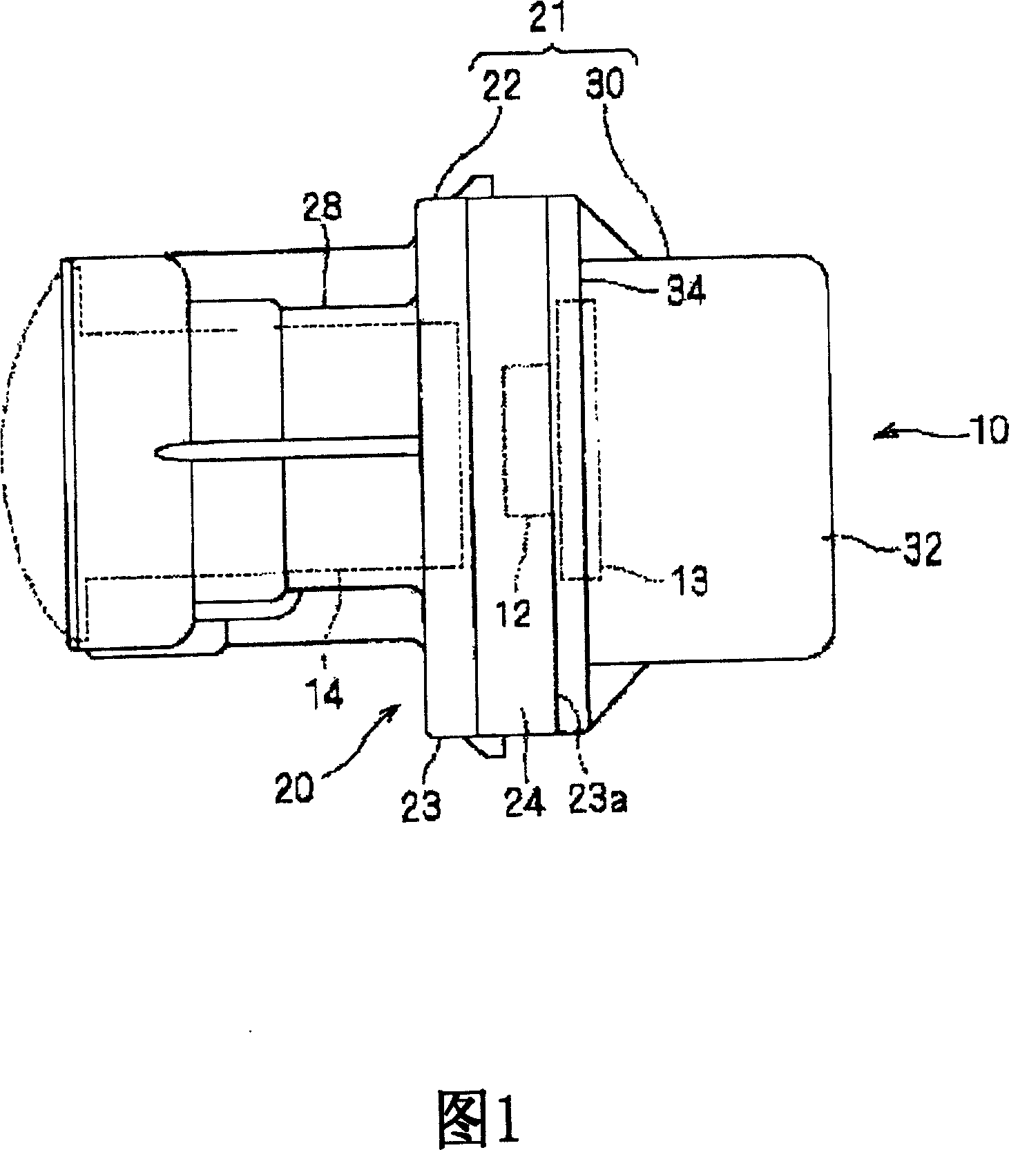
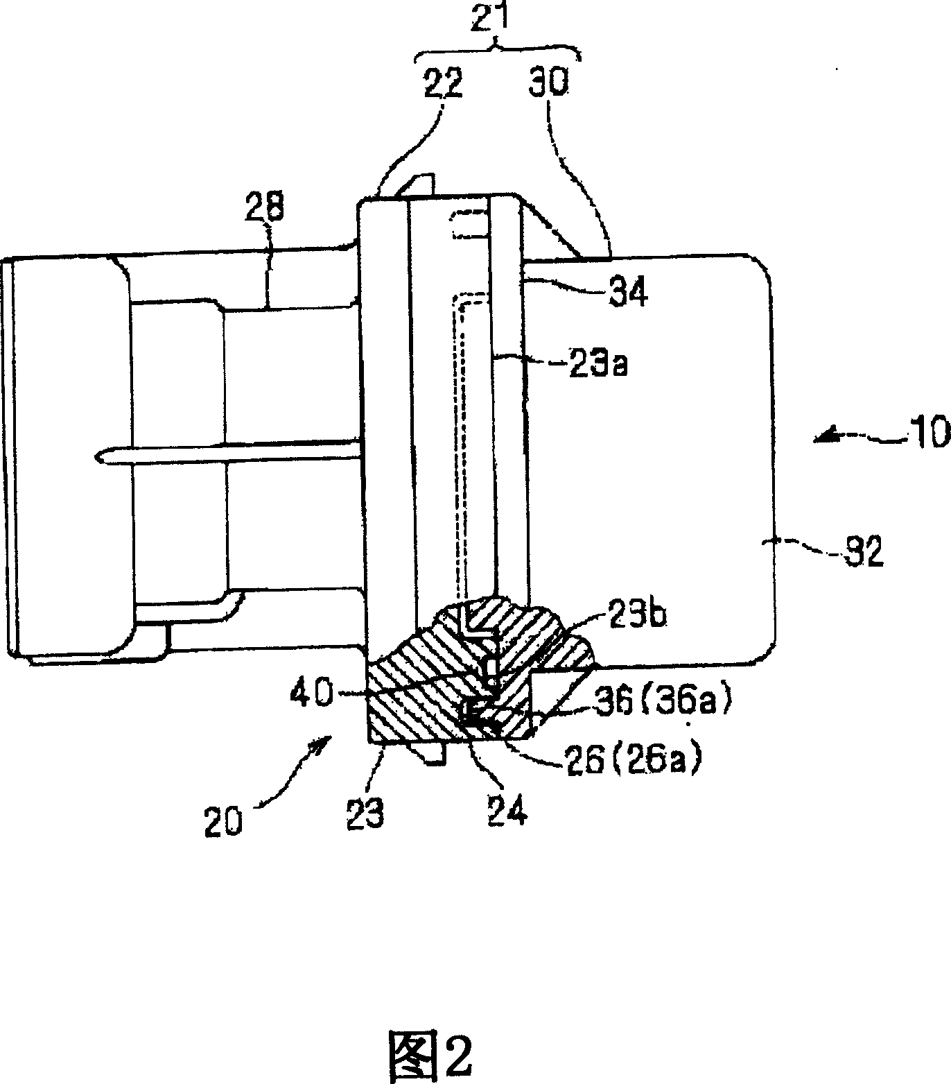
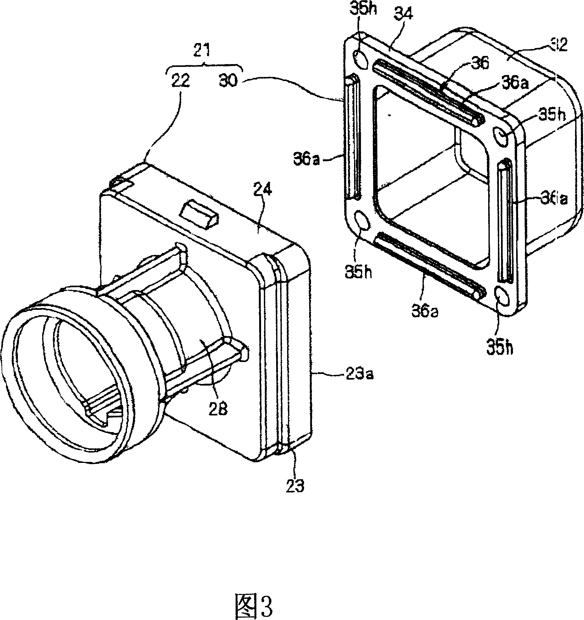
[0024] Next, a waterproof case for a vehicle-mounted camera and a camera device according to an embodiment of the present invention will be described. Fig. 1 is a side view showing a waterproof case for a camera device, Fig. 2 is a partially cut-away sectional view showing the waterproof case, Fig. 3 is an exploded perspective view of the waterproof case seen from the oblique front, and Fig. 4 is a perspective view of the waterproof case viewed from the oblique rear An exploded perspective view of the waterproof case. In addition, for convenience of description, the image side (lens side) is referred to as the front side, and the imaging surface side (imaging element side) is described as the rear side.

[0025] Furthermore, the vehicle-mounted camera 10 to which this waterproof case 20 is applied is installed, for example, outside the vehicle body such as the front, rear, or side of the vehicle. Furthermore, a wide area including the left and right sides of the front of the ...


PUM


Abstract

A waterproof case for an in-vehicle camera includes a front case part and a rear case part, and houses imaging means such as the imaging device therein. A packing member is set between the front case part and the rear case part, and waterproofs and seals the space therebetween. A water-stop wall part is protrudingly formed on a flange part which is an attaching portion of the rear case part at a peripheral of the packing member. A concave part, into which the water-stop wall part can be fitted, is formed on an opening peripheral part which is an attaching portion of the front case part.

Description

technical field [0001] The present invention relates to a technique for waterproofing an on-vehicle camera installed outside a vehicle. Background technique [0002] A technique is known in which a vehicle-mounted camera installed outside the vehicle captures a scene around the vehicle, especially a blind-spot area, and displays it on a display device inside the vehicle. [0003] Such an on-vehicle camera is installed outside the vehicle body, and therefore requires strong waterproof performance. [0004] A conventional waterproof structure generally has a structure in which a packing is interposed between a front case and a rear case which are housings of a vehicle-mounted camera, and the two cases are fixed with screws. [0005] However, the above-mentioned conventional waterproof structure is a structure in which the packing is compressed and interposed between the front case and the rear case, so a slight gap is formed at the junction of the front case and the rear case...

Claims


Application Information

Patent Timeline
Patent Type & Authority Applications(China)
IPC IPC(8): B60R11/04
CPCB60R13/06B60R11/04H04N23/51H04N23/57
Inventor 井本政善小池正敏
Owner AUTONETWORKS TECH LTD
Why Eureka
Try Eureka