Detecting method and equipment for digital wave filter

A digital filter and detection method technology, applied in the direction of measuring devices, digital technology networks, instruments, etc., can solve the problems of high positioning implementation cost and large chip resource consumption, so as to reduce design cost, simple implementation scheme, and less resource consumption Effect

Active Publication Date: 2007-03-07
新东港控股集团有限公司
View PDF0 Cites 3 Cited by
  • Summary
  • Abstract
  • Description
  • Claims
  • Application Information

AI Technical Summary

Problems solved by technology

[0013] The purpose of the present invention is to provide a digital filter detection method, which aims to solve the problem of high cost of detection or problem location in the prior art that consumes a lot of chip resources when detecting digital filters

Method used


Image

  • Detecting method and equipment for digital wave filter
  • Detecting method and equipment for digital wave filter
  • Detecting method and equipment for digital wave filter

Examples


Embodiment Construction

[0054] In order to make the object, technical solution and advantages of the present invention clearer, the present invention will be further described in detail below in conjunction with the accompanying drawings and embodiments. It should be understood that the specific embodiments described here are only used to explain the present invention, not to limit the present invention.

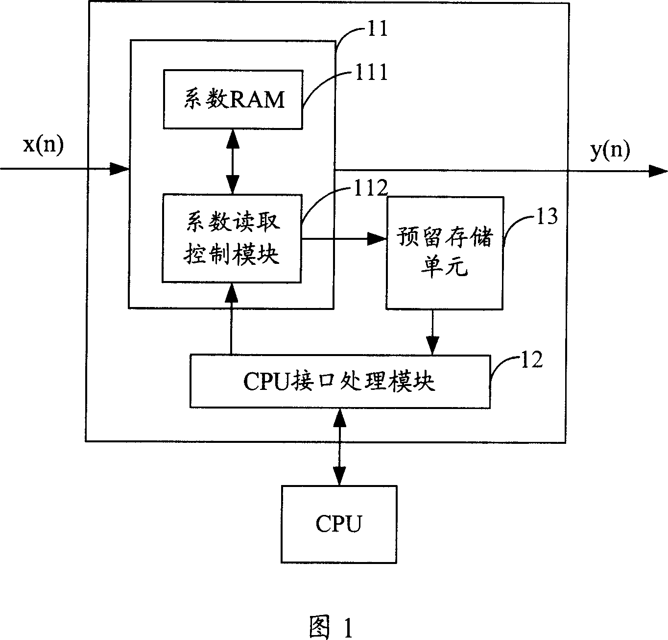
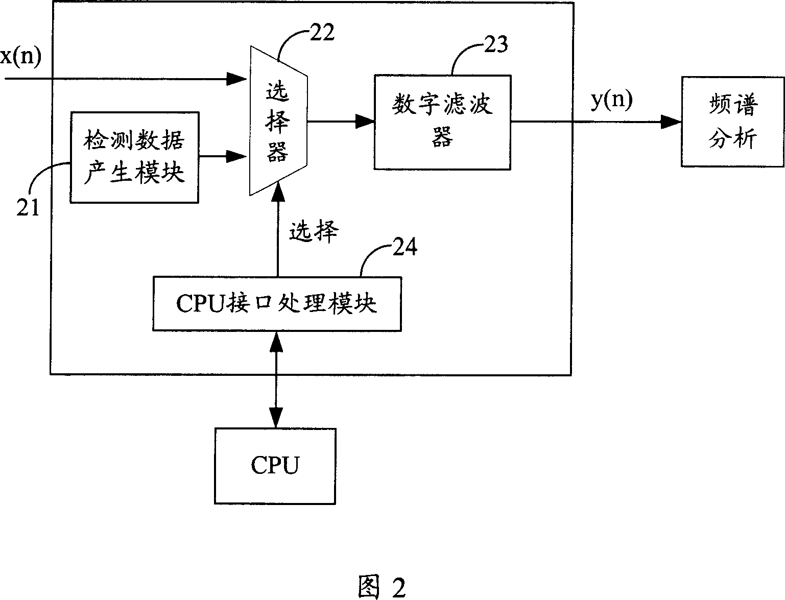
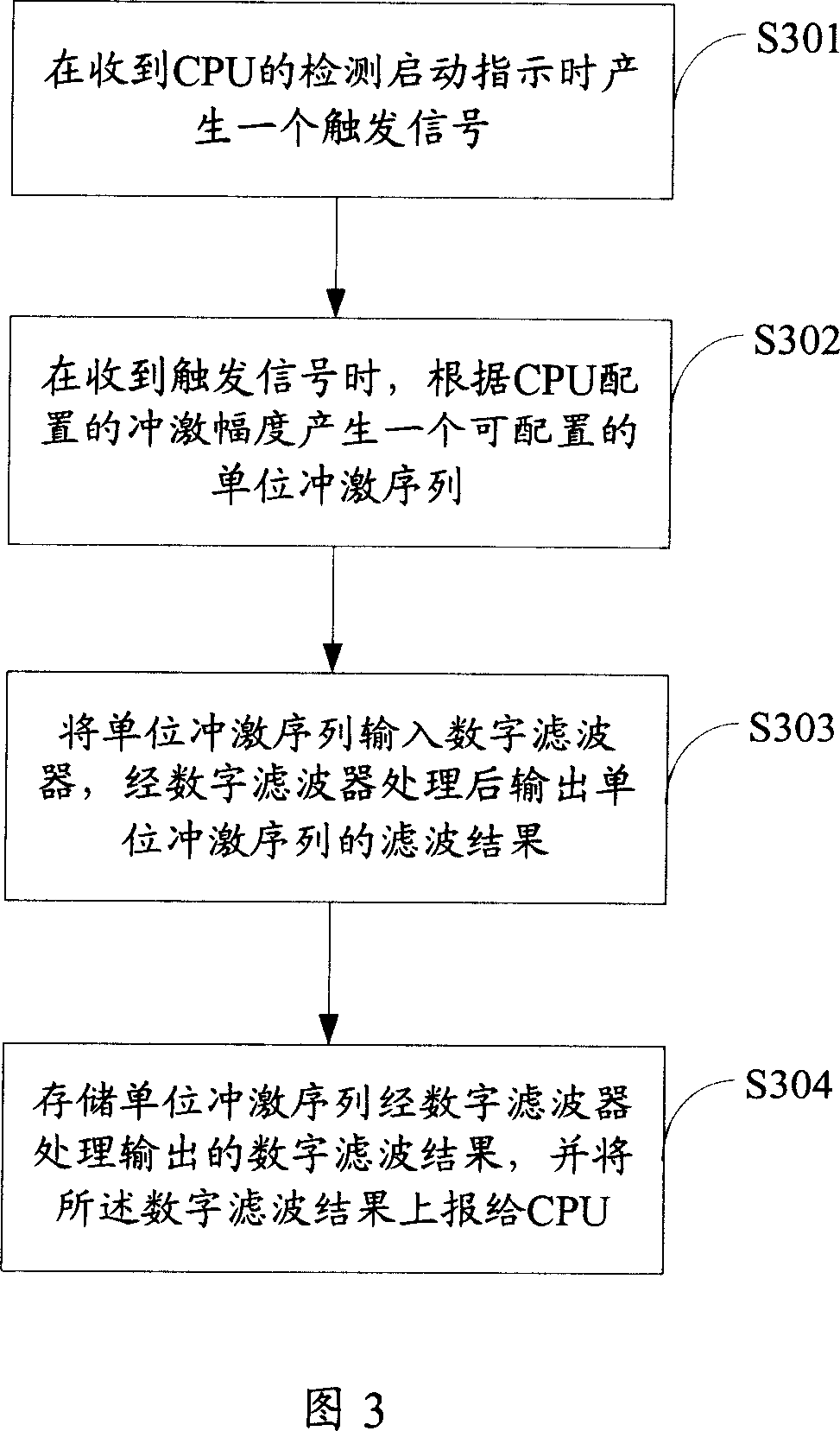
[0055] The present invention is based on the principle that the transfer function of the linear system can be obtained through the unit impulse response, by adding an impulse sequence at the input end of the digital filter, and judging whether the digital filter works normally according to the saved output result of the digital filter.

[0056]Taking the FIR filter as an example, the unit impulse sequence δ(n) is input to the digital filter, and the unit impulse sequence δ(n) can be expressed by the following formula:

[0057] δ(n)=1, (when n=0);

[0058] δ(n)=0, (when n≠0).

[0059] It represent...


PUM


Abstract

This invention relates to signal filter test method and device in signal process field, wherein the method comprises the following steps: a, generating one trigger signal when receiving the indication; b, when receiving trigger signal, generating one unit impulse sequence according to the matched range; c, inputting the said unit laser sequence to the digital filter; d, when receiving the trigger signal, storing the said unit sequence digital filter result; e, analyzing whether the digital filter is normal according to the said filter result.

Description

technical field [0001] The invention belongs to the field of digital signal processing, and in particular relates to a detection method and device of a digital filter. Background technique [0002] Digital filtering is widely used in the field of digital signal processing, and it cooperates with other algorithm processing to realize complex digital signal processing functions. A digital filter can be expressed as follows: [0003] y(n)=b(1)*x(n)+b(2)*x(n-1)+...+b(nb+1)*x(n-nb)-a(2)* y(n-1)-...-a(na+1)*y(n-na) [0004] Among them, n-1 is the order of the digital filter, and the above formula is applicable to both the Finite Impulse Response (FIR) filter and the Infinite Impulse Response (IIR) filter structure. [0005] In the above formula, when a(2)~a(na+1) are all zero, y(n) can be expressed as [0006] y(n)=b(1)*x(n)+b(2)*x(n-1)+...+b(nb+1)*x(n-nb), [0007] At this time, the output signal y(n) is only related to the limited input signal "x(n)~x(n-nb)", and the filter...

Claims


Application Information

Patent Timeline
Patent Type & Authority Applications(China)
IPC IPC(8): G01R31/00G01R31/28H03H17/02
Inventor 徐争
Owner 新东港控股集团有限公司
Why Eureka
Try Eureka