
Highly sensitive airflow direction sensing

a sensing and airflow technology, applied in ventilation systems, heating types, combustion failure safes, etc., can solve the problems of insufficiently high sensitivity and reliability of sensors, inability to implement, install and/or adapt in various applications, and inability to meet the needs of safety, etc., to achieve high reliability and sensitive, simple to implement, install and/or adap

Inactive Publication Date: 2011-08-23
HABEGGER MILLARD A
View PDF6 Cites 23 Cited by
  • Summary
  • Abstract
  • Description
  • Claims
  • Application Information

AI Technical Summary

Benefits of technology

[0007]This invention provides sensors / apparatus and methods well suited to a number of applications requiring a highly reliable and sensitive determination of airflow direction between two volumes, for example in a combustion flue to indicate positive and negative pressure differentials between the interior and exterior of a facility. The sensors / apparatus are adaptable for utilization of a single sensor system wide in a combustion appliance assemblage, are simple to implement, install and / or adapt in various applications, and are relatively inexpensive.
[0008]The sensors / apparatus and methods of this invention enhance combustion appliance safety, are responsive to dangerous conditions before they become a threat to occupants, and are remediative in nature. The sensor / apparatus provides means adaptable for response to low flue / chimney draft type pressure differentials and for differentiating flue draft airflow direction, thereby enhancing occupant safety by reliably indicating and responding to negative indoor pressure with respect to the outdoors in facilities / homes using modern combustion appliances. The sensor / apparatus and methods of this invention provide a heretofore unavailable simple, reliable, self-contained digital electrical signal indicative of proper and improper flue draft with a high degree of sensitivity (+ / −0.001 inches of water column).
[0019]It is yet another object of this invention to provide sensors / apparatus for application in facilities / homes using combustion appliances to enhance occupant safety by reliably indicating and responding to negative indoor pressure with respect to the outdoors.
[0020]It is still another object of this invention to provide sensors / apparatus that are adaptable so that a single sensor may be utilized system wide in a combustion appliance assemblage, that are simple to implement, install and / or adapt in various applications, and that are inexpensive.

Problems solved by technology

Such sensors are responsive to dangerous conditions only after the conditions are present in a facility and a threat to occupants, are of debatable sensitivity and reliability, are not remediative, and are thus less than adequate solutions to the safety problem.
To date, such a sensor with sufficiently high sensitivity and reliability has not existed.
While useful, such approaches have required draft sensing at each combustion appliance and have not been simple to implement, install and / or adapt in various applications.
Under current building codes, the needed airflow requires either very large ducts or very streamlined high velocity ducts, both of which are expensive to provide and install and consume valuable building space.
But, as noted heretofore, no such sensing solution has been forthcoming, and suitable pressure sensors (having adequate sensitivity) have not been available.

Method used


Image

  • Highly sensitive airflow direction sensing
  • Highly sensitive airflow direction sensing
  • Highly sensitive airflow direction sensing

Examples


Embodiment Construction

[0032]A preferred embodiment of this invention is illustrated in the FIGURES, which is illustrated and discussed for utilization in conjunction with a facility combustion appliance flue. Other applications of the sensor / apparatus and methods of this invention could be conceived as will be apparent from the description. As this description proceeds, the term “airflow” is utilized but should be understood to mean not only the flow of air, but the flow of any gaseous substances between two volumes (this definition is also applicable to the claims).

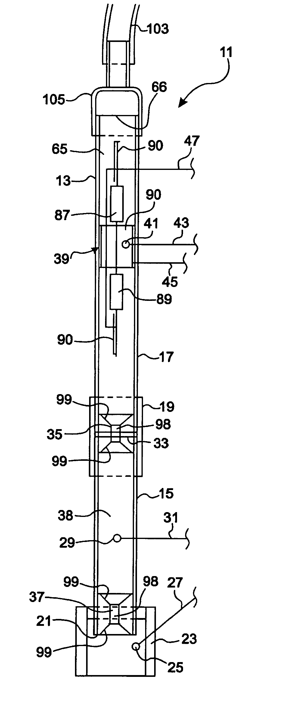
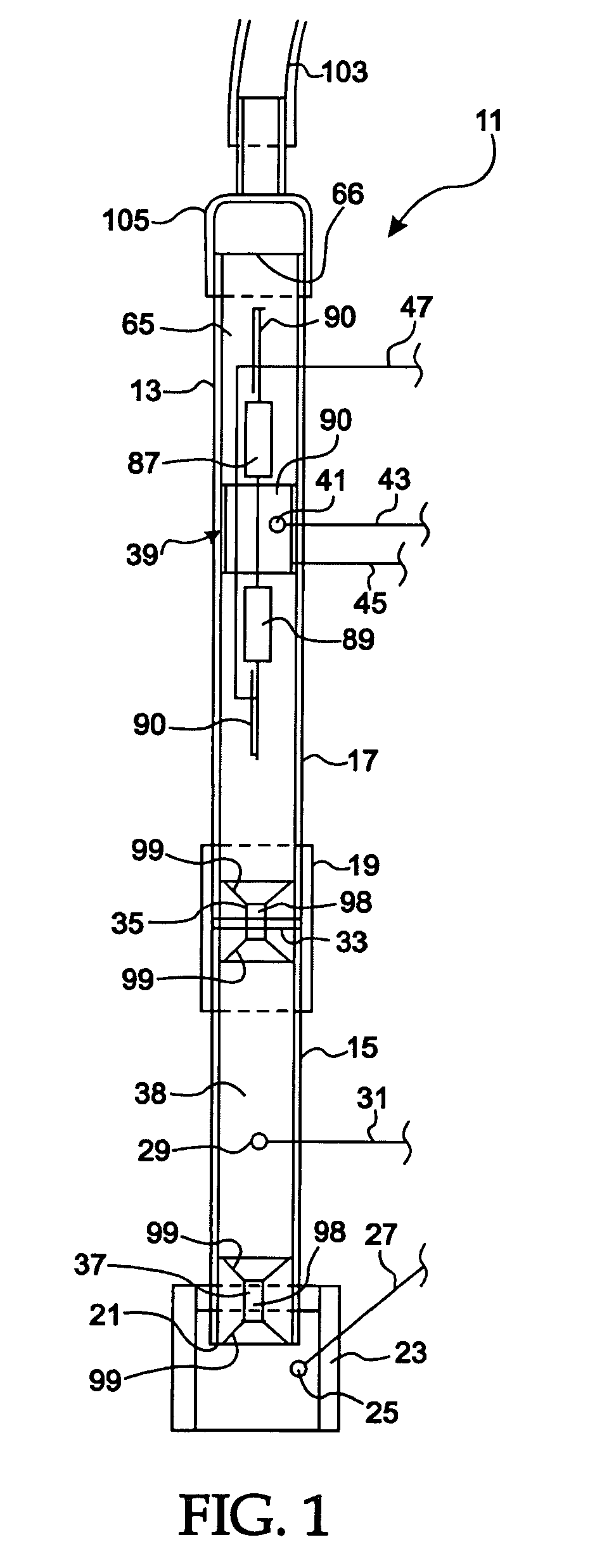
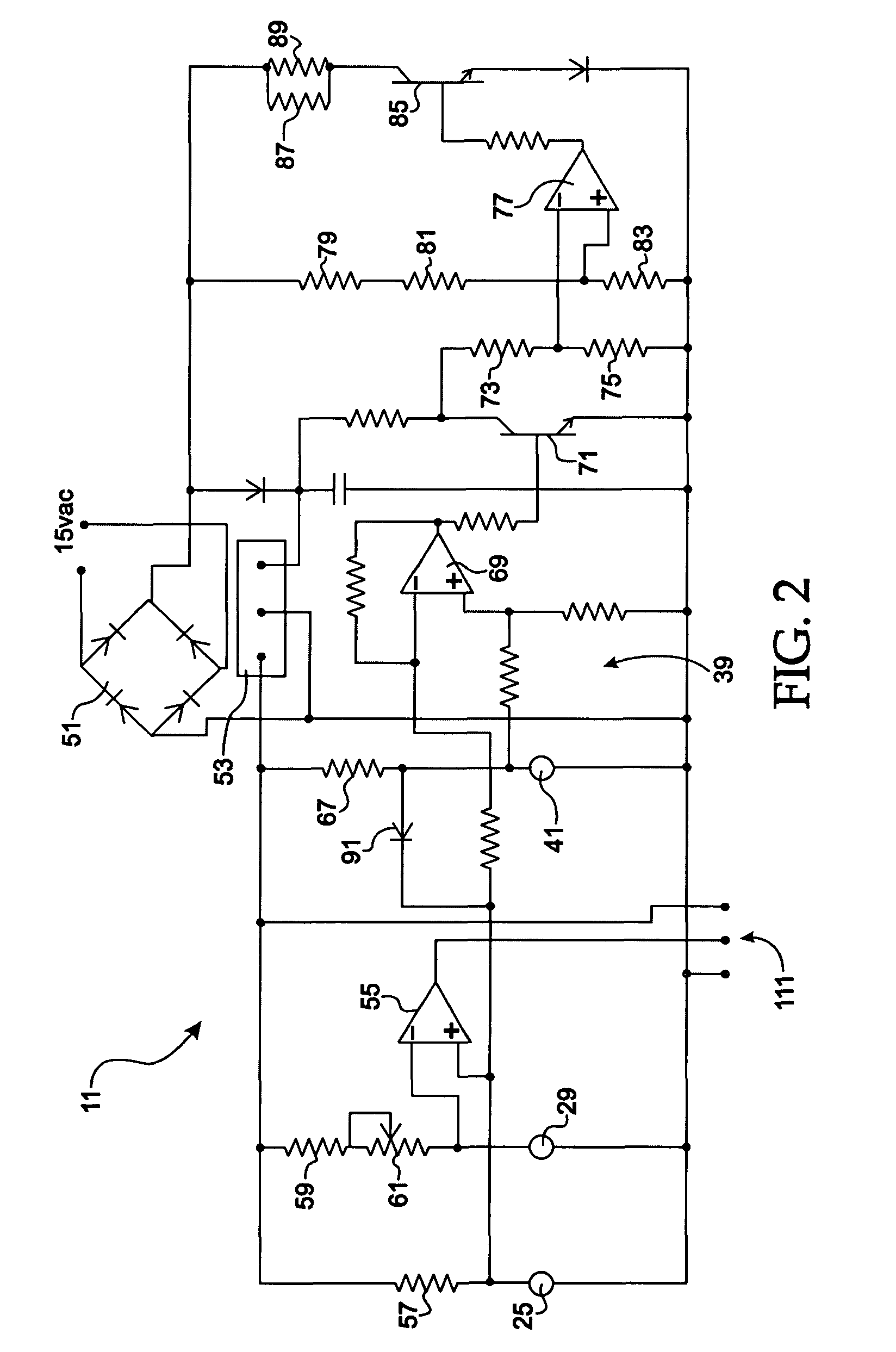
[0033]Turning now to the drawings, sensing apparatus 11 (also referred to herein as “sensor 11”) is illustrated in FIGS. 1 and 2. Short tube 13 provides an airflow passage therethrough for conducting air or other gases between two volumes. Tube 13 in the illustrated application is adapted and oriented to conduct a stream of air or other gases between a flue and the ambient environment in which a combustion appliance is located. Tube 13 is pre...


PUM


Abstract

Sensors, apparatus and methods are disclosed for detecting airflow direction between two volumes. The preferred airflow sensor includes a tube for conducting an airflow stream between the volumes, a first temperature sensor sensing ambient temperature in the first volume and a second temperature sensor sensing temperature of the airflow stream in the tube. A heat source heats air in the tube adjacent the end thereof communicating with the second volume and a comparator receives and compares output signals from the temperature sensors, providing an output indicative thereof. Various means are provided responsive to the output advancing appropriate response thereto. The disclosed sensors, apparatus and methods are particularly well adapted for indicating positive and negative pressure differentials at flues associated with combustion appliances.

Description

FIELD OF THE INVENTION[0001]This invention relates to airflow direction sensing, and, more particularly, relates to airflow direction sensing between different volumes of air.BACKGROUND OF THE INVENTION[0002]Air and water heating and conditioning appliances utilizing gas combustion are in extensive usage worldwide, and their safe installation and use in occupied facilities is of ongoing concern. This concern has led, for example, to an entire industry based on sensing the presence of carbon monoxide in the occupied portions of such facilities. Such sensors are responsive to dangerous conditions only after the conditions are present in a facility and a threat to occupants, are of debatable sensitivity and reliability, are not remediative, and are thus less than adequate solutions to the safety problem.[0003]A goal of some in the industry has been to provide means making facility / home HVAC safety sensor based rather than containment based (through the use of air ducts and the like). M...

Claims


Application Information

Patent Timeline
Patent Type & Authority Patents(United States)
IPC IPC(8): F24F7/00G01F13/00G01F5/00
CPCF23N5/242F23N2025/06F23N2031/18F23N2031/26F23N2225/06F23N2231/26F23N2231/18
Inventor HABEGGER, MILLARD A.
Owner HABEGGER MILLARD A
Learn More