
Degaussing circuit

A technology of degaussing circuit and circuit, which is applied in the direction of using cathode camera tube image reproducer, picture duplicator, etc., which can solve the problems of inability to perform degaussing and deterioration of color purity of TV sets, etc.

Inactive Publication Date: 2007-03-07
KK TOSHIBA
View PDF2 Cites 0 Cited by
  • Summary
  • Abstract
  • Description
  • Claims
  • Application Information

AI Technical Summary

Problems solved by technology

The problem is that even if the color purity of the TV is deteriorated due to geomagnetism etc. when the user transports the TV with the power turned on, the necessary degaussing cannot be performed.

Method used


Image

  • Degaussing circuit
  • Degaussing circuit
  • Degaussing circuit

Examples


no. 1 approach

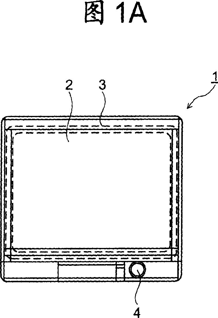
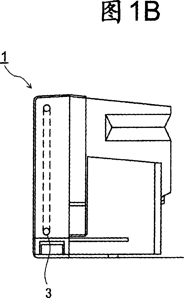
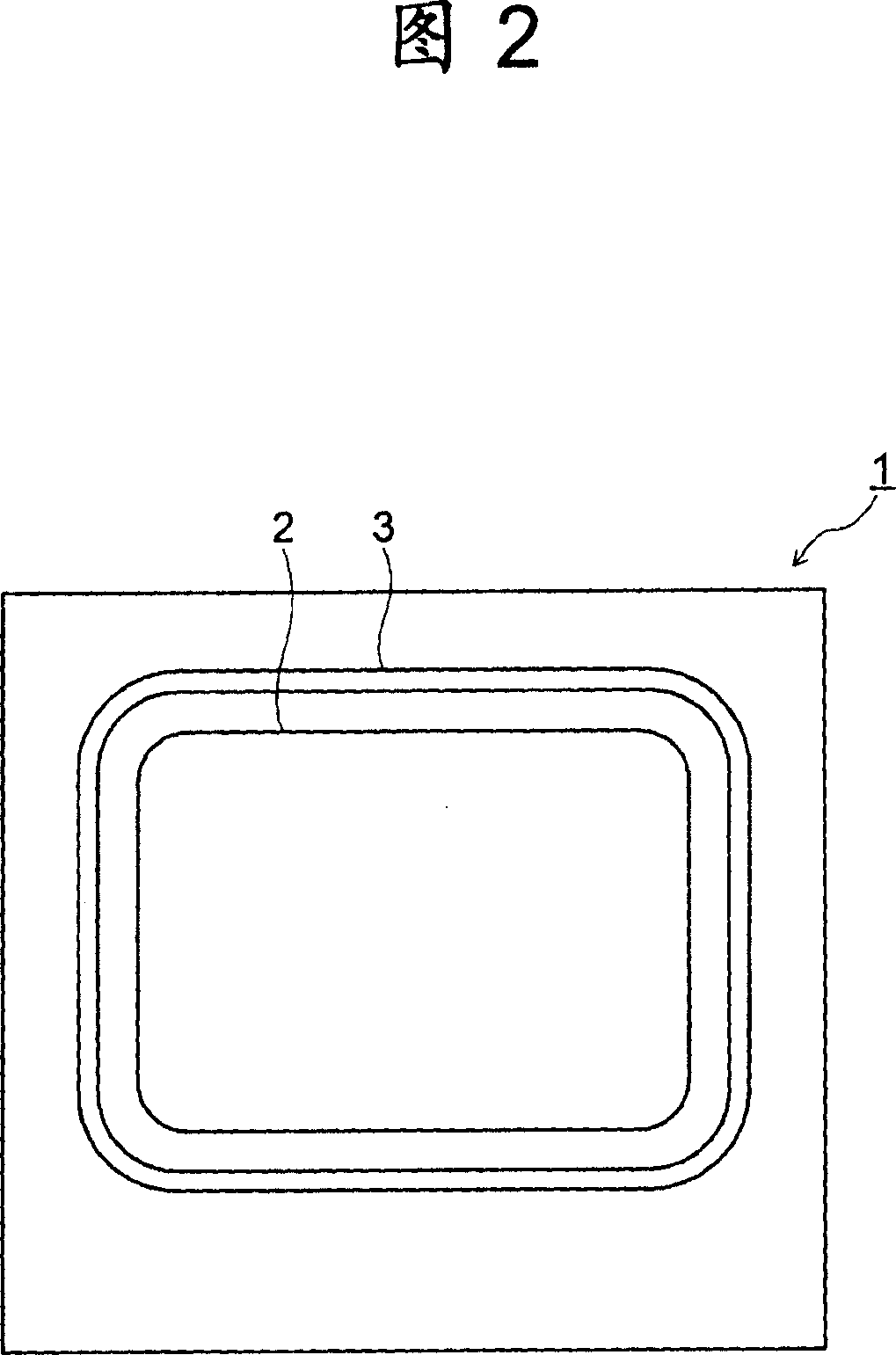
[0018] A first embodiment of a degaussing circuit according to the present invention will be described with reference to FIGS. 1A and 1B to 3 . An example in which the degaussing circuit is applied to a television will be described below. 1A and 1B are external views of the television 1, with Fig. 1A being a front view and Fig. 1B being a side view. The television set 1 has a structure in which a video display surface of a cathode ray tube (Braun tube) 2 is located in front and a degaussing coil 3 is introduced in such a manner as to surround the cathode ray tube 2 in the television set 1 . The degaussing manual switch 4 is connected to the bottom of the TV set 1 front cover. A structural portion showing the state of the degaussing coil 3 installed in the cathode ray tube 2 is shown as a schematic diagram of the television 1 in FIG. 2 .

[0019] Figure 3 is a block diagram of the degaussing circuit. The main body of the degaussing circuit includes: a degaussing circuit 3 su...

no. 2 approach

[0029] A second embodiment of the degaussing circuit according to the present invention will be described with reference to FIGS. 1A and 1B , 2 and 4 . Note that descriptions of the same parts as in the first embodiment will be omitted.

[0030] Figure 4 is a block diagram of the degaussing circuit. The difference between FIG. 4 and FIG. 3 is that a manual switch 10 is provided instead of the switch 7 , the control circuit 8 and the degaussing start signal input 9 . The manual switch 10 has a configuration of a relay circuit together with, for example, a button. Manual switch 10 may consist of a solid state switch made of semiconductors or the like.

[0031] The operation of the degaussing circuit according to this embodiment will be discussed. The user operates the manual switch 10 to initiate degaussing, whereby the manual switch 10 is turned off. The OFF state is completed by the ON operation of the manual switch 10 performed by the user and becomes the ON state. There...


PUM


Abstract

Provided is a demagnetizing circuit which is capable of carrying out a necessary demagnetization process when a television set is deteriorated in color purity in the case that the television set is brought in by a user as its power supply is kept in an on-state. The demagnetizing circuit is equipped with a demagnetizing coil connected to a DC power supply, a parallel circuit unit composed of a capacitor and a resistor and connected to one end of the demagnetizing coil whose other end is connected to the power supply, and a manual switch which is connected to one end of the parallel circuit whose other end is connected to the demagnetizing coil. The one side of the manual switch whose other side is connected to the parallel circuit is connected to the ground.

Description

[0001] Cross References to Related Applications [0002] The present application is based upon and claims the benefit of priority of prior Japanese Patent Application No. 2005-249443 filed on Aug. 30, 2005; the entire contents of which are incorporated herein by reference. technical field [0003] The present invention relates to a degaussing circuit, and more particularly, to a degaussing circuit capable of repeated degaussing. Background technique [0004] Conventionally, various types of degaussing circuits for degaussing cathode ray tubes of so-called DC input televisions and the like using a DC power source as a power source have been proposed. [0005] For example, a degaussing circuit disclosed in Japanese Utility Model Application Laid-Open No. 6-41289 (see page 2 and FIG. 1) has a degaussing coil and a capacitor connected in parallel as main circuit elements, whereby degaussing is achieved by using The resulting oscillating electromagnetic field performs. [0006]...

Claims


Application Information

Patent Timeline
Patent Type & Authority Applications(China)
IPC IPC(8): H04N9/29
Inventor 中山佳行
Owner KK TOSHIBA
Learn More