Inductance energy-releasing swashing current-generator
A current generator and inductance technology, applied in the field of impulse current generators, can solve the problems of difficult implementation in general enterprise laboratories, high working voltage, and inability to test voltage clamping characteristic components such as piezoresistors, etc., to achieve manufacturing Low cost and daily operation and maintenance costs, low voltage change speed, and the effect of reducing production costs and maintenance costs
- Summary
- Abstract
- Description
- Claims
- Application Information
AI Technical Summary
Problems solved by technology
Method used
Image
Examples
Embodiment 1
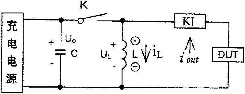
[0038] attached Figure 5 Is an embodiment of the present invention, and in this example, the current control device KI is a freewheeling diode D, among which DUT is a test object, L is a waveform inductance, C is an energy storage capacitor, and K is a discharge switch of the energy storage capacitor, The charging power supply is any form of DC adjustable power supply. When working, first charge C with the required voltage Uo from the charging power source, then press the start button AN, switch K1 through the control circuit KZ, and discharge the capacitor C to the inductor L. After the charge stored on C is discharged, When the inductance L generates a back EMF, a current is pushed to flow through the object under test DUT and the freewheeling diode D, and the waveform of the current is determined by the impedance characteristics of the inductance L and the DUT.
Embodiment 2
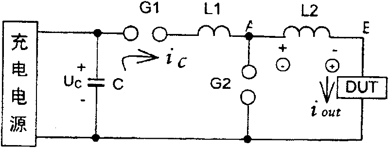
[0040] attached Figure 6 It is another embodiment of the present invention. In this example, the current control device KI is the trigger ball gap G2, and the capacitive discharge switch is the trigger ball gap G1. Press the start button AN, the trigger circuit Tr1 outputs an ignition pulse to G1, so G1 breaks down and conducts, and the capacitor C discharges to the inductor L. After the charge stored on C is discharged, the inductor L generates a counter electromotive force. This counter electromotive force makes The trigger circuit Tr2 outputs an ignition pulse to G2, so G2 breaks down and conducts, and the inductance L pushes a current to flow through the DUT and the ball gap G2 to form the required current wave. The diode D in the figure blocks the discharge voltage of the capacitor C from entering Tr2.
PUM
 Abstract
Description
Claims
Application Information
 - R&D
- Intellectual Property
- Life Sciences
- Materials
- Tech Scout
- Unparalleled Data Quality
- Higher Quality Content
- 60% Fewer Hallucinations
Browse by: Latest US Patents, China's latest patents, Technical Efficacy Thesaurus, Application Domain, Technology Topic, Popular Technical Reports.
© 2025 PatSnap. All rights reserved.Legal|Privacy policy|Modern Slavery Act Transparency Statement|Sitemap|About US| Contact US: help@patsnap.com


