Heat exchanger header tank and heat exchanger comprising same

A technology for heat exchangers and header boxes, which is applied to heat exchange equipment, heat exchanger shells, evaporators/condensers, etc., can solve the problems of difficulty in manufacturing, low efficiency, and troublesome installation of spacers, and achieves a reduction in the number of Effect

Inactive Publication Date: 2007-03-14
SHOWA DENKO KK
View PDF1 Cites 20 Cited by
  • Summary
  • Abstract
  • Description
  • Claims
  • Application Information

AI Technical Summary

Problems solved by technology

[0006] However, the header tank included in the heat exchanger of this publication requires a cover for closing the openings at both ends, and thus has the problem that the number of components must increase, and for joining the cover to the header, Inefficiency in the work of connecting the tubes to the plate and the intermediate plate
Additionally, the cover must be made as a separate piece and is difficult to manufacture
[0007] In order to improve the heat exchange performance of the heat exchanger disclosed in the gazette, it is desired to change the flow route of the refrigerant, for example, by partitioning the inside of at least one header tank with a partition, but this brings about the problem that the arrangement of the partition troublesome process

Method used


Image

  • Heat exchanger header tank and heat exchanger comprising same
  • Heat exchanger header tank and heat exchanger comprising same
  • Heat exchanger header tank and heat exchanger comprising same

Examples


Embodiment 1

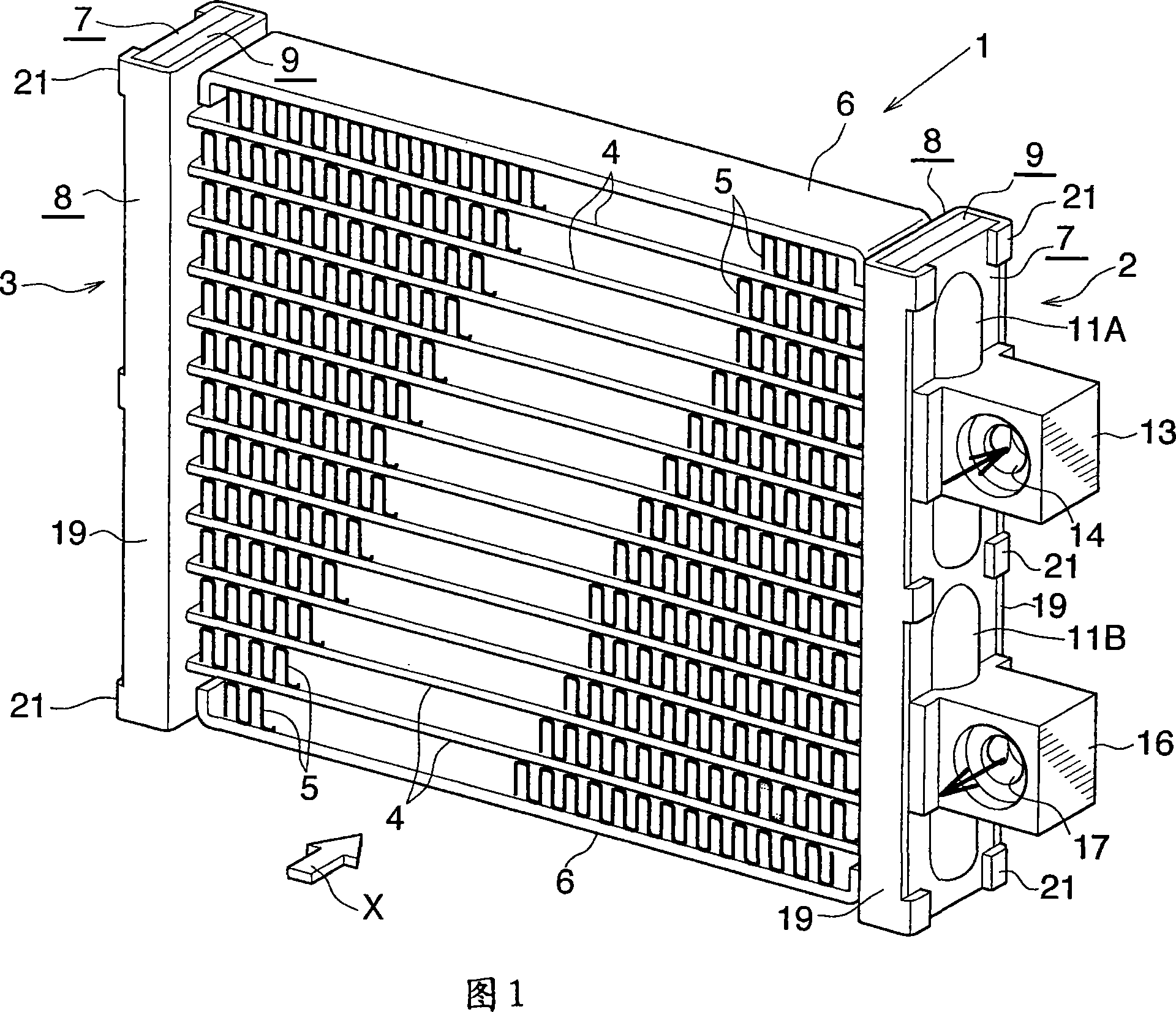
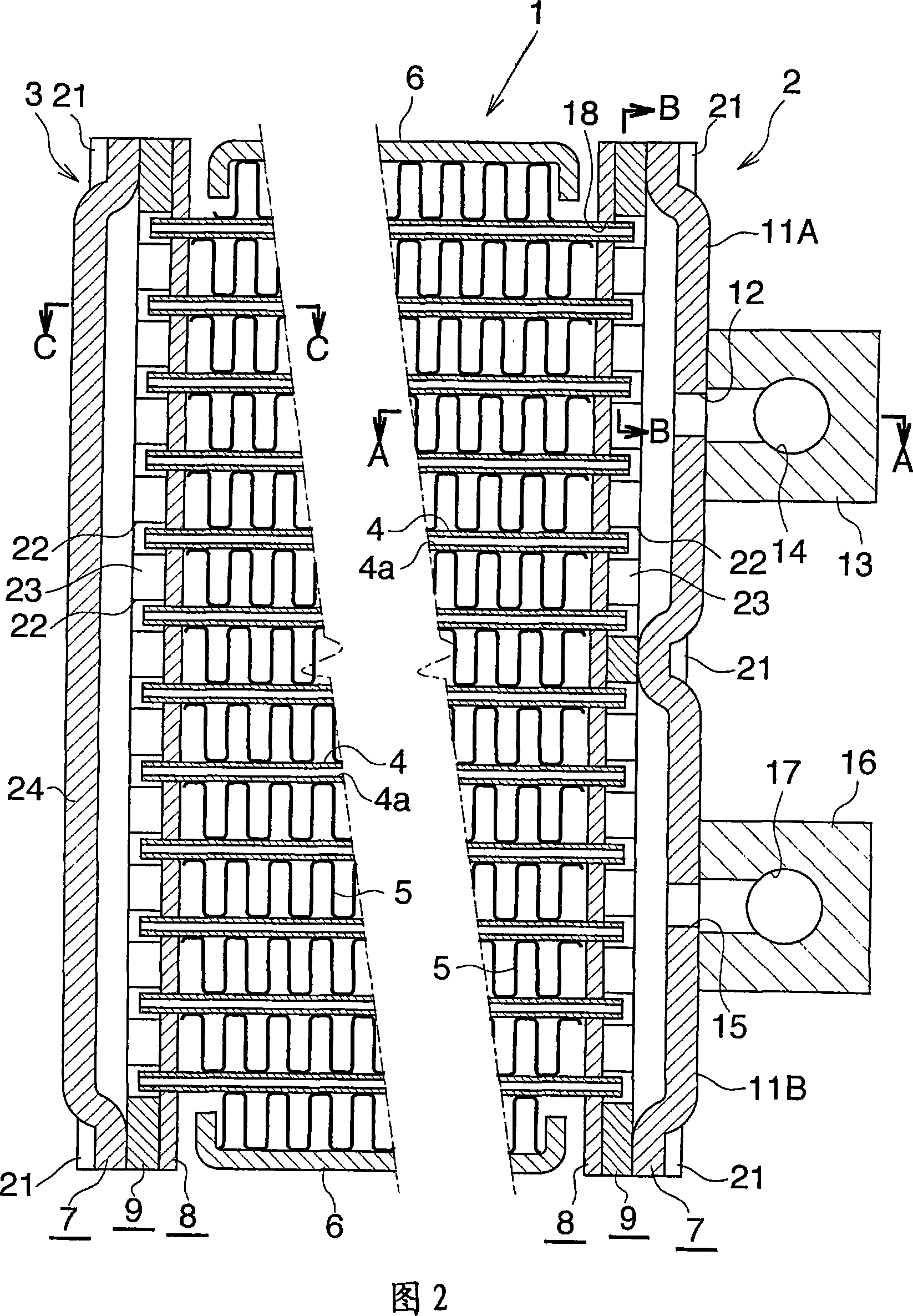
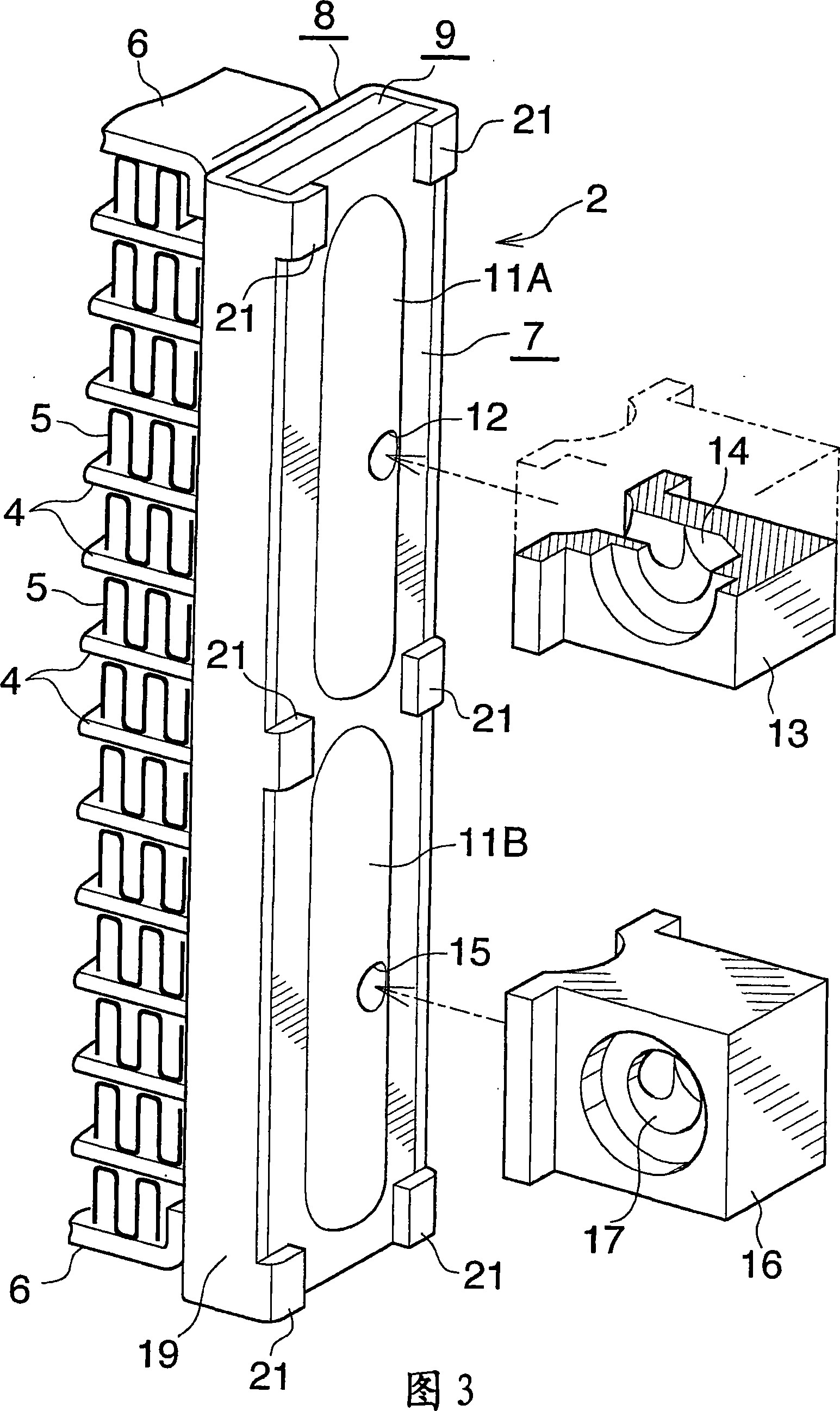
[0079] This embodiment is shown in Figures 1 to 9 and is a gas cooler for a supercritical refrigeration cycle comprising the heat exchanger of the present invention.

[0080] Referring to Figure 1, for where a supercritical refrigerant such as CO is used 2The gas cooler 1 of the supercritical refrigerating cycle includes two header boxes 2, 3 extending upward or downward and arranged at intervals along the left and right directions, and one at an interval between the two header boxes 2, 3 A plurality of flat heat exchange tubes 4, corrugated fins 5 and side plates 6 arranged in parallel on one side, the corrugated fins are arranged in each air passing gap between adjacent pairs of heat exchange tubes 4 and The outer sides of the heat exchange tubes 4 located at the upper and lower ends of the cooler, and each fin is brazed on the adjacent pair of heat exchange tubes 4 or end tubes 4, the side plates are made of bare aluminum The material is made and placed externally and braz...

Embodiment 2

[0096] This embodiment is shown in Figures 10 to 20 and comprises a heat exchanger of the invention suitable for use as an evaporator in a supercritical refrigeration cycle.

[0097] Referring to Figures 10 to 12, for where a supercritical refrigerant such as CO is used 2 The evaporator 30 of the supercritical refrigerating cycle includes two header tanks 31, 32 extending in the left-right direction and spaced up or down. A plurality of flat heat exchange tubes 33, corrugated fins 34 and aluminum side plates 35 are arranged, and the corrugated fins are arranged in each air passage gap between adjacent pairs of heat exchange tubes 33 and in the evaporation The outside of the heat exchange tubes 33 at the left and right ends of the device, and each fin is brazed on the adjacent pair of heat exchange tubes 33 or end tubes 33, the side plates are set and brazed on the left and right ends. The corresponding fins 34 at the exterior. In the case of this embodiment, the upper header...


PUM


Abstract

A heat exchanger 1 has header tanks 2, 3 each comprising a header forming plate 7, a tube connecting plate 8 and an intermediate plate 9 interposed between these two plates 7, 8, the plates 7, 8, 9 being arranged in superposed layers and brazed to one another. Each of the plates 7, 8, 9 is made from a metal plate by press work. The header forming plate 7 has outward bulging portions 11A, 11B or an outward bulging portion 24. The tube connecting plate 8 has tube insertion holes 18. The intermediate plate 9 has communication holes 22 for causing tube insertion holes 18 to communicate with the interior of each outward bulging portion 11A, 11B or 24 therethrough. Heat exchange tubes 4 have opposite ends placed into the respective insertion holes 18 and brazed to the respective tube connecting plates 8. The heat exchanger comprising such header tanks 2, 3 is reduced in the number of components, can be fabricated with a high work efficiency and exhibits improved heat exchange performance.

Description

[0001] Cross References to Related Applications [0002] This application was filed pursuant to 35 U.S.C. §111(a) and was filed pursuant to 35 U.S.C. §119(e)(1) on March 24, 2004 and February 24, 2005 under 35 U.S.C. §111(b) Filing-date benefits of filed provisional applications No. 60 / 555,705 and No. 60 / 555,426. technical field [0003] The present invention relates to a header box for a heat exchanger and a heat exchanger comprising the header box, and in particular to a header box and a heat exchanger for a heat exchanger such as a gas cooler or an evaporator of a supercritical refrigeration cycle, in The supercritical refrigeration cycle uses CO 2 (carbon dioxide) refrigerant or similar supercritical refrigerant. [0004] Herein and in the appended claims, the term "aluminum" includes aluminum alloys in addition to pure aluminium. Background technique [0005] There is known a heat exchanger for a supercritical refrigeration cycle, which includes a pair of header tank...

Claims


Application Information

Patent Timeline
Patent Type & Authority Applications(China)
IPC IPC(8): F28F9/02F25B1/00F25B39/02F25B39/04F28F21/08
Inventor 一柳茂治
Owner SHOWA DENKO KK
Why Eureka
Try Eureka