Holding resuming device for recording head and image forming device

A recording head and image technology, applied in printing and other directions, can solve the problems of long action time, short viscosity time of fluidity, difficult to remove, etc., to achieve simple structure, prevent pollution and reduce image quality, and prolong the effect of time

Inactive Publication Date: 2007-03-21
RICOH KK
View PDF3 Cites 15 Cited by
  • Summary
  • Abstract
  • Description
  • Claims
  • Application Information

AI Technical Summary

Problems solved by technology

Compared with general dye-based inks, such pigment-based inks have a higher viscosity and a shorter time for the solvent components to evaporate to a viscosity that loses fluidity, so they remain on the downstream end of the nozzle surface in the wiping direction (wiping rear end). ) residual ink is not easy to remove
[0013] At this time, according to the wiping device described in the above-mentioned Patent Document 2, although there is a mechanism for removing the residual ink on the side of the recording head by using the back surface of the wiping member (wiping member), it needs to perform wiping counting and position control, so its operation time is relatively long. long
Moreover, since it is a mechanism in which the transfer action is greater than the wiping action, there is a problem that it is difficult to remove paper dust and the like from the edge of the nozzle surface of the recording head.
On the other hand, due to the user's frequency of use, the wiping action interval also changes, so there is a problem that the adhesion state of the remaining ink also changes, and the normal wiping action cannot be performed.
[0014] In addition, according to the device described in Patent Document 3, since the device has many components and the wiping direction is along the longitudinal direction of the recording head, there is a problem that the required operation time is long.

Method used


Image

  • Holding resuming device for recording head and image forming device
  • Holding resuming device for recording head and image forming device
  • Holding resuming device for recording head and image forming device

Examples


Embodiment Construction

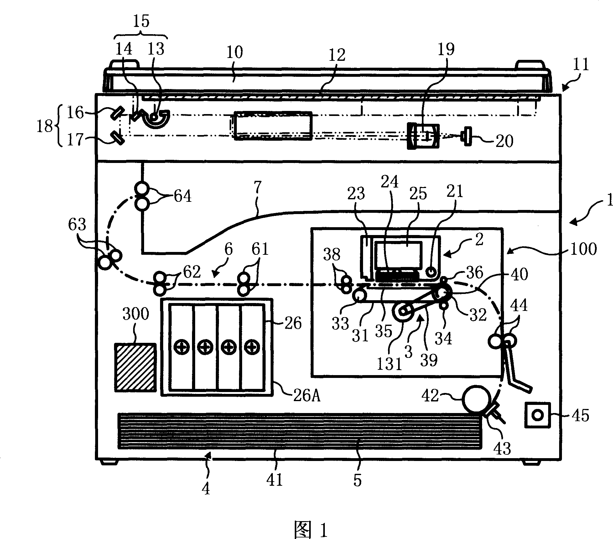
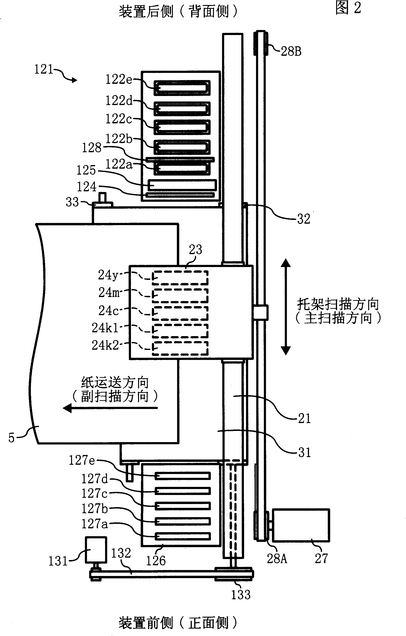
[0043] Hereinafter, embodiments of the present invention will be described with reference to the drawings. An example of the image forming apparatus of the present invention will be described with reference to FIGS. 1 and 2 . FIG. 1 is a schematic configuration diagram showing the overall configuration of the image forming apparatus, and FIG. 2 is an explanatory plan view of an image forming unit and a sub-scanning transfer unit of the apparatus.

[0044] This image forming apparatus includes an image forming section (means, device) 2 for forming an image, a sub-scanning transport section (means, device) 3, and the like inside the apparatus main body 1 (inside the housing). From the paper feeding part (means, device) 4 as a storage device provided at the bottom of the device body 1, a recording medium (hereinafter referred to as "paper" as a conveyed member, but its material is not limited to paper) 5 is fed one by one. The paper is separated and fed, and while the paper 5 is...


PUM


Abstract

A recording head maintenance recovery mechanism and image forming apparatus, the maintenance recovery mechanism (121) has: caps 122a-122e for sealing the nozzle surface (24a) of the recording head (24), and a wiping sheet for wiping the nozzle surface (124), have simultaneously the nozzle surface (24a) that is arranged along the lengthwise direction of wiping sheet (124), the nozzle surface (24a) of the recording head (24) of relative stop moves up and down and will remain on the nozzle surface (24a) of recording head (24) A removal member (128) for removing residual recording liquid at the end portion on the downstream side in the wiping direction. Therefore, it is possible to prevent image disturbance and contamination inside the device due to residual recording liquid at the end of the nozzle surface after the wiping of paper dust or the like adhering to the wiping of the recording head.

Description

technical field [0001] The present invention relates to a recording head maintenance and recovery device and an image forming device. Background technique [0002] As image forming apparatuses such as printers, facsimile machines, copiers, and their multifunction machines, for example, inkjet recording apparatuses are known as image forming apparatuses of a liquid discharge recording method using a recording head that discharges recording liquid droplets. The inkjet recording device transfers recording liquid such as ink droplets from the recording head to the conveyed paper (not limited to paper, but refers to materials including OHP and other ink droplets or other liquids that can be attached, and can also be referred to as being recorded. medium or recording medium, recording paper, recording paper, etc.) to form an image (synonymous recording, printing, copying, printing), including the serial type with the recording head moving in the main scanning direction and the use...

Claims


Application Information

Patent Timeline
Patent Type & Authority Applications(China)
IPC IPC(8): B41J2/165
Inventor 渡辺贤
Owner RICOH KK
Why Eureka
Try Eureka