Intelligent door lock

A smart door lock and microprocessor technology, applied in the field of door locks, can solve the problems of unsafe and inconvenient door locks, and achieve the effect of strong confidentiality and simple operation

Active Publication Date: 2007-03-21
ZHEJIANG KINGKIND IND & TRADE
View PDF0 Cites 11 Cited by
  • Summary
  • Abstract
  • Description
  • Claims
  • Application Information

AI Technical Summary

Problems solved by technology

[0003] The purpose of the present invention is to provide an intelligent door lock to solve technical problems such as insecurity and inconvenience in the prior art door locks

Method used


Image

  • Intelligent door lock
  • Intelligent door lock

Examples


Embodiment Construction

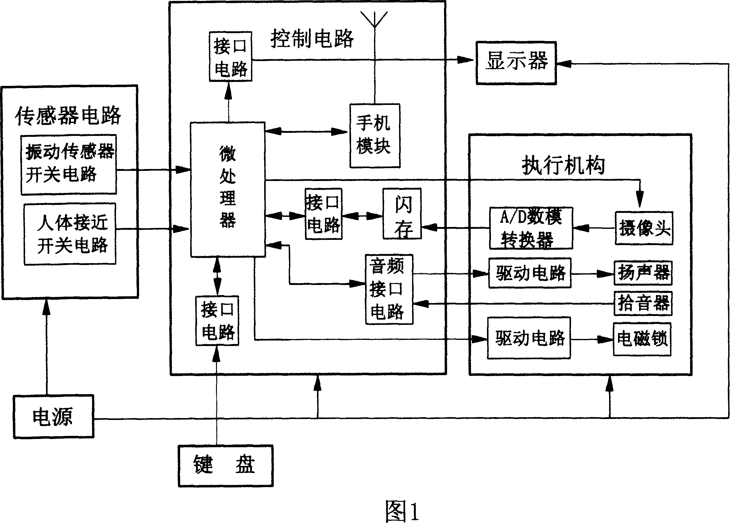
[0015] According to the intelligent door lock shown in Figure 1, it is mainly composed of a display, a power supply, a control circuit, a keyboard, an execution part, and a sensor circuit.

[0016] The control circuit is mainly composed of a mobile phone module, a microprocessor, an interface circuit, and a flash memory. The mobile phone module includes a radio frequency circuit, a SIM card interface circuit, etc., and a CPU. High-frequency amplification, receiving local oscillator, frequency mixing, transmitting local oscillator, power amplifier control, power amplifier and other small circuits. The microprocessor adopts single-chip microcomputer, which is 8051 series, 89C, AT89C2051 and other series single-chip microcomputers. Its main function is to exchange data and control the normal operation of each part.

[0017] The power supply is an AC-to-DC regulated power supply, which is always connected in parallel with a rechargeable lithium battery to prevent the door from be...


PUM


Abstract

The present invention relates to an intelligent door lock. It includes the following several portions: power supply, display, control circuit, keyboard, actuating mechanism and sensor circuit. The described control circuit includes handset module capable of transmitting and receiving handset short message, microprocessor, flash memory and several interface circuits, in the handset module interior a SIM card interface circuit is set, the described handset module and sensor circuit are connected with microprocessor. Said microprocessor is respectively connected with keyboard, flash memory, display and actuating mechanism by means of interface circuits.

Description

technical field [0001] The invention relates to a door lock, in particular to an intelligent door lock. Background technique [0002] Now, there are many door locks for anti-theft, such as tumbler locks, magnetic locks, and electronic locks. The most common is a pin mechanical lock. Several pins of different heights are arranged in the lock cylinder, which can be opened with a key of a corresponding shape. Because the number of marbles is limited and the height and position are limited, it is easier to open with some unlocking tools, such as hooks; at the same time, once the key is lost or used, it is easy to be copied, and the only solution is to replace the door lock. The principle of the magnetic lock is similar to that of the tumbler lock, except that several magnetic columns arranged in specific magnetic poles are used instead of the tumbler. With the development of electronic technology, electronic locks have also developed many varieties, such as IC card locks, digi...

Claims


Application Information

Patent Timeline
IPC IPC(8): E05B49/00
Inventor 李书浩
Owner ZHEJIANG KINGKIND IND & TRADE
Why Eureka
Try Eureka