Hydraulic relief valve

A safety valve, hydraulic technology, applied in the field of hydraulic safety valve, can solve the problems of reduced supply function, complex structure, difficult assembly and so on

Inactive Publication Date: 2007-03-21
SAMSUNG HEAVY IND CO LTD
View PDF1 Cites 10 Cited by
  • Summary
  • Abstract
  • Description
  • Claims
  • Application Information

AI Technical Summary

Problems solved by technology

As a result, the pressure in the tank-side flow channel 4 that performs replenishment of the hydraulic fluid is increased to prevent insufficient flow, thereby generally degrading its replenishment function.
[0015] Moreover, since the outer spring 70 and the inner spring 80 are installed in a narrow space, the structure will be quite complicated, and its assembly will be difficult.
In addition, due to the interference between the springs, it will cause operational obstruction

Method used


Image

  • Hydraulic relief valve
  • Hydraulic relief valve
  • Hydraulic relief valve

Examples


Embodiment Construction

[0027] In the following, preferred embodiments of the present invention will be described with reference to the accompanying drawings. The content defined in the specification, such as detailed structures and elements, are only specific details provided to help those of ordinary skill in the art fully understand the present invention, so the present invention is not limited to these specific details.

[0028] The structure of the hydraulic safety valve according to the present invention will now be described in detail in conjunction with preferred embodiments.

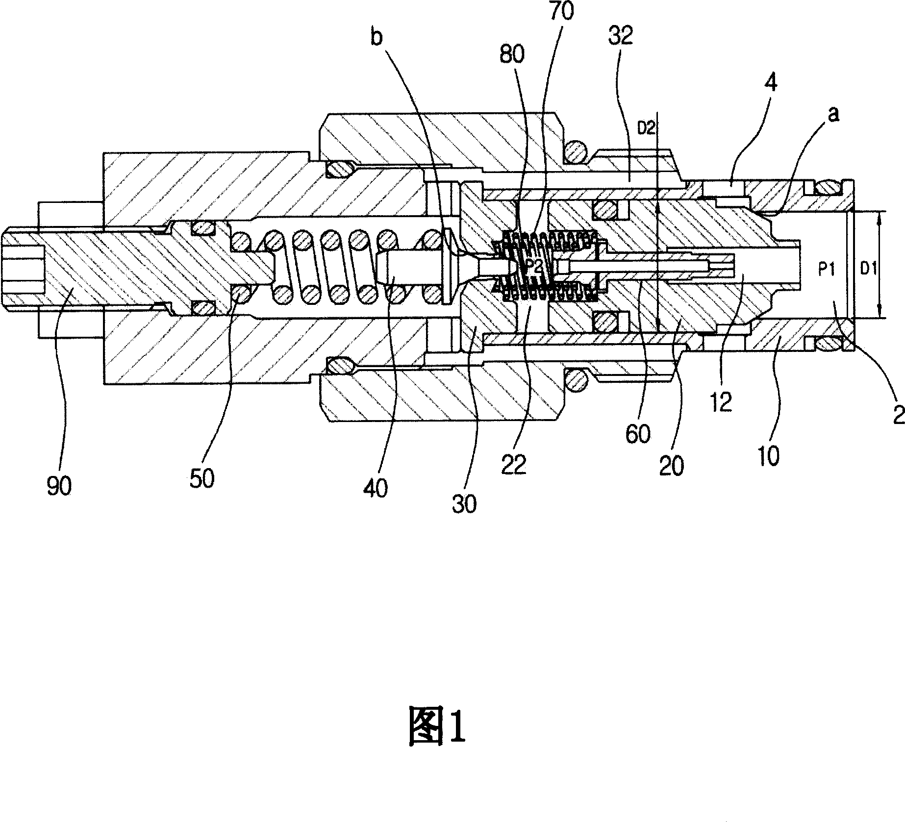
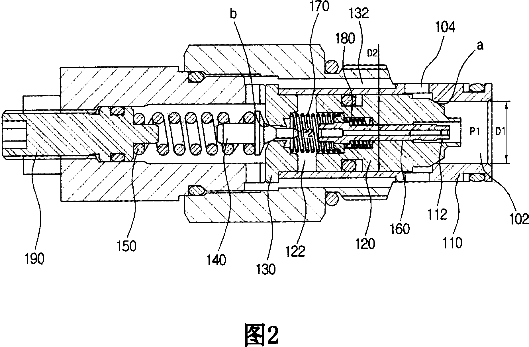
[0029] Fig. 2 is a cross-sectional view describing the structure of a hydraulic safety valve according to the present invention.

[0030] 2, the hydraulic safety valve includes: a sleeve 110 having a high-pressure flow passage 102 formed on one side of the sleeve 110 through which hydraulic fluid flowing out of the hydraulic pump P flows through the high-pressure flow passage of the high pressure P1, and A container-side f...


PUM


Abstract

A hydraulic relief valve has a spring to offset an acting force of a spring resiliently supporting a main poppet so as to improve the make-up function of supplementing a hydraulic fluid since the outflow rate is higher than the inflow rate when the cylinder is retracted by an external force, in the case in which a pilot piston type of relief valve having a pilot piston displaceable in an orifice penetrating a main poppet is applied to a hydraulic system equipped with a cylinder. The pilot piston is provided with a circular rib on an external surface thereof, and an external surface of the orifice is partially cut to form a space around the external surface of the pilot piston. The external spring is installed between the valve seat and the external surface of the rib, and the internal spring is installed between the internal surface of the rib and the cut surface of the main poppet.

Description

[0001] Cross-references to related applications [0002] This application is based on Korean Patent Application No. 10-2005-86047 filed with the Korean Patent Office on September 15, 2005, and claims the priority of this application, the disclosure of which is incorporated herein by reference. Technical field [0003] The present invention relates to a hydraulic safety valve, and more specifically to a hydraulic safety valve with a spring, which is used to offset the force of the spring that elastically supports a main poppet valve, so as to apply a guide piston type safety valve to the assembly with In the case of the hydraulic system of the cylinder, the replenishment function of the hydraulic fluid that needs to be supplemented when the cylinder is retracted under the action of external force to make the outflow greater than the inflow is improved. Among them, the safety valve has a pipe that can penetrate the main poppet valve. Guide piston moving in the hole. Background techn...

Claims


Application Information

Patent Timeline
Patent Type & Authority Applications(China)
IPC IPC(8): F15B20/00
CPCF16K17/105Y10T137/7766F16K17/04F16K27/02F16K1/34F16K1/36
Inventor 郑海均
Owner SAMSUNG HEAVY IND CO LTD
Why Eureka
Try Eureka