Lower vehicle body structure

A body, front and rear technology of the body, applied in the substructure, superstructure, subassembly of the superstructure, etc., can solve the problem of strength of other components that are not mentioned

Inactive Publication Date: 2007-03-28
MAZDA MOTOR CORP
View PDF1 Cites 26 Cited by
  • Summary
  • Abstract
  • Description
  • Claims
  • Application Information

AI Technical Summary

Problems solved by technology

However, the bracket disclosed in this gazette is only suitable for utilizing the strength of the beam, and does not mention the further utilization of the strength of other components

Method used


Image

  • Lower vehicle body structure
  • Lower vehicle body structure
  • Lower vehicle body structure

Examples


Embodiment Construction

[0031] Hereinafter, embodiments of the present invention will be described in detail with reference to the accompanying drawings. However, the present invention is not limited to the following embodiments, and only specific examples useful for carrying out the present invention are shown below. In addition, all the combinations of the features described in the following embodiments are not necessarily all necessary components to solve the problems of the present invention.

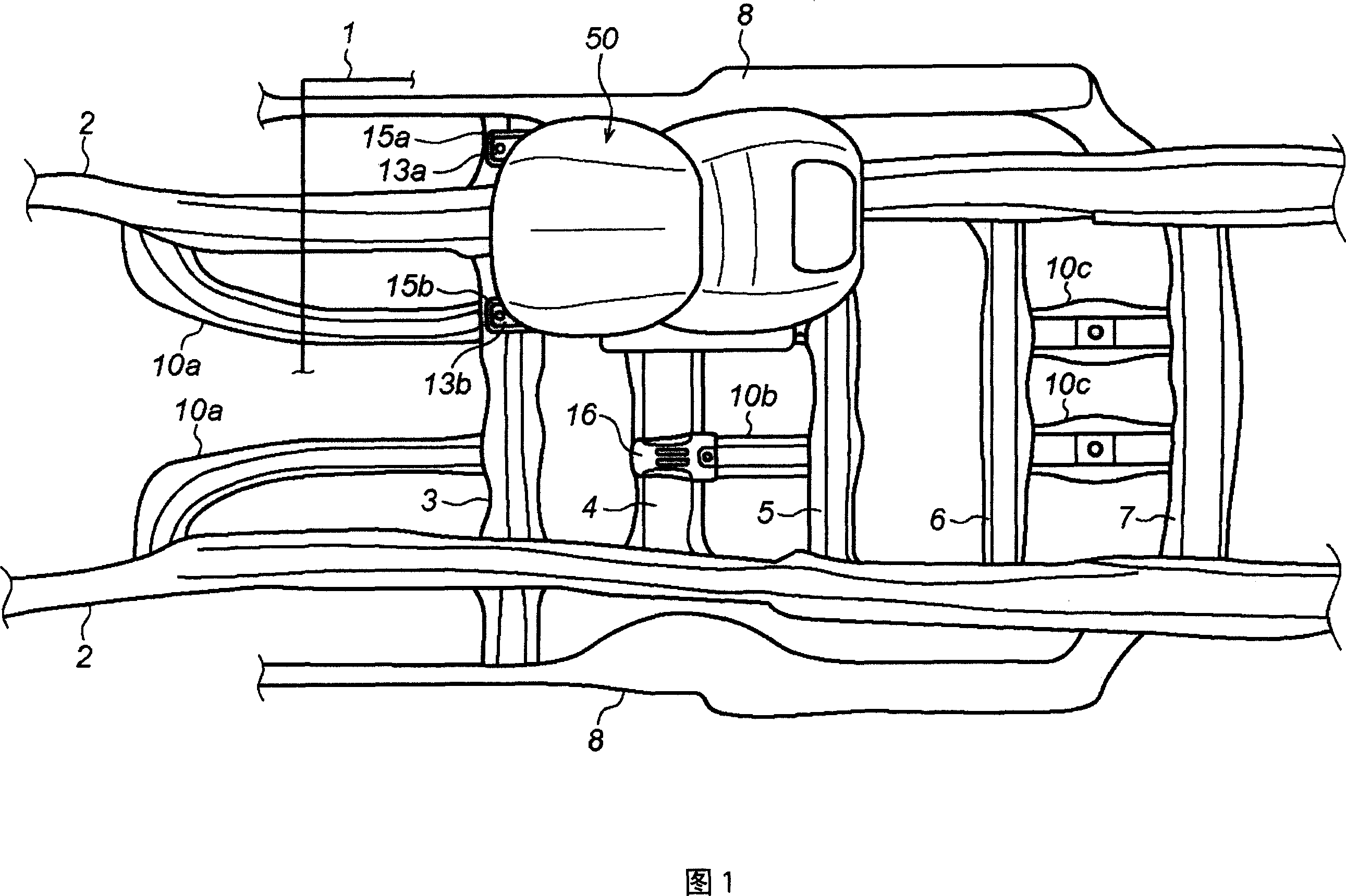
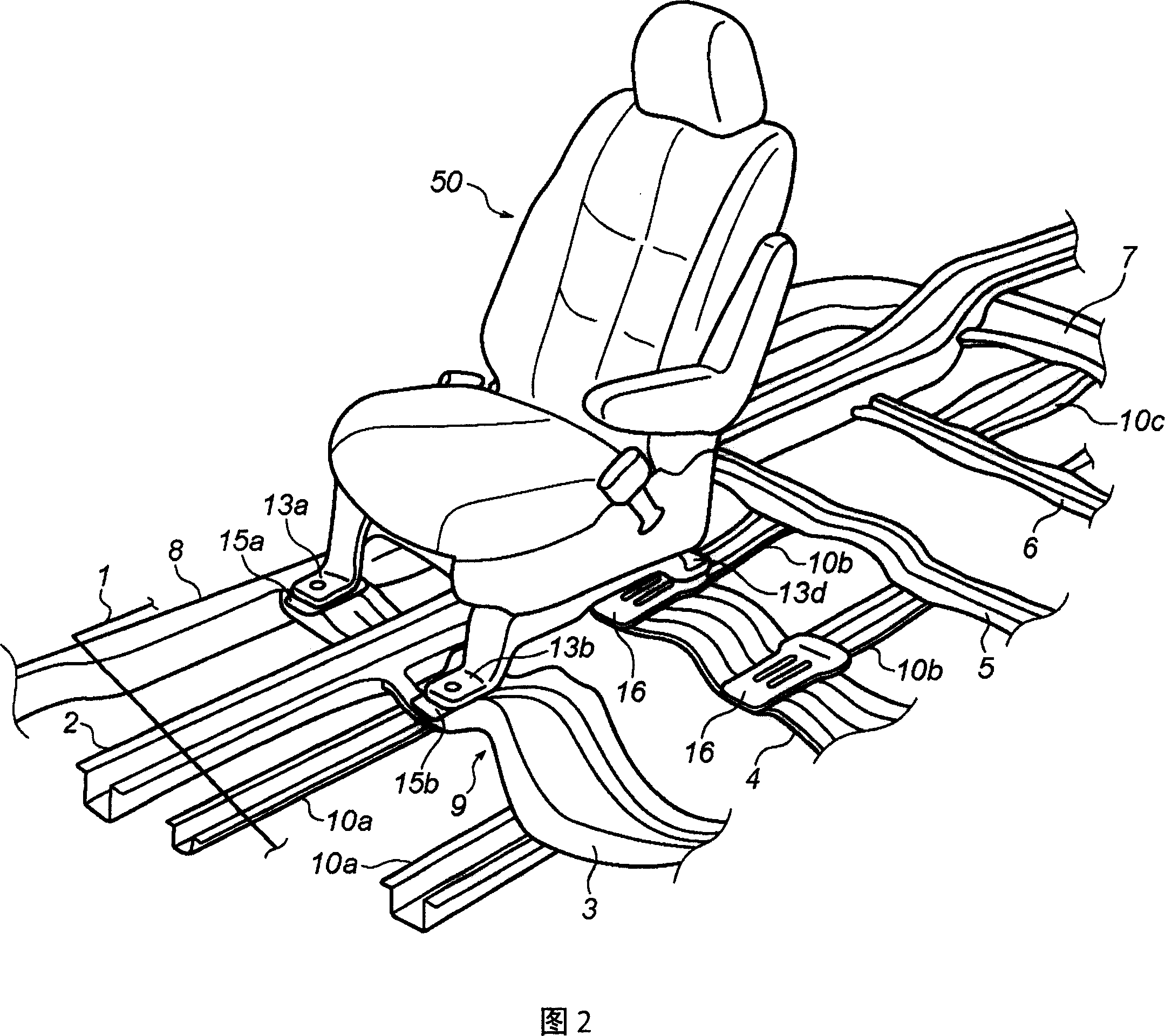
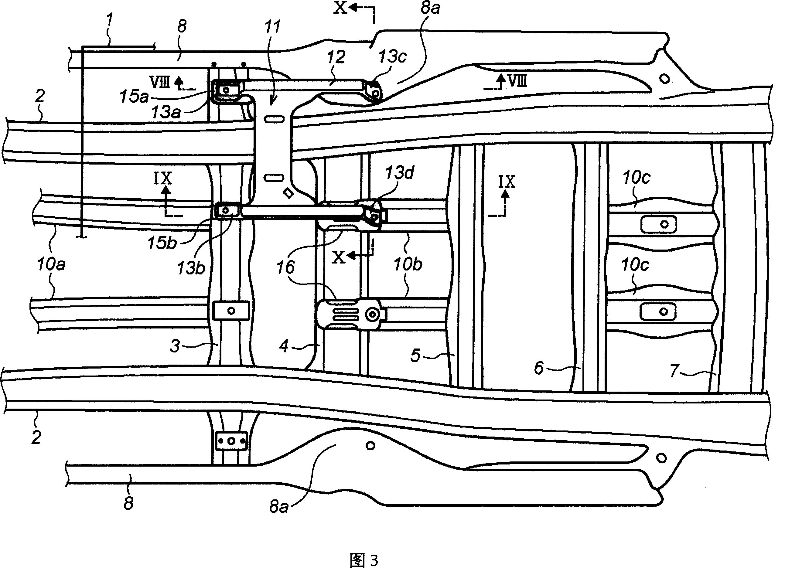
[0032] First, referring to FIGS. 1 to 3 , the lower body structure of the present embodiment will be briefly described. FIG. 1 is a plan view showing a lower body structure of the present embodiment, and for convenience of description, a state where only the right front seat 50 is attached is shown. FIG. 2 is a perspective view of the lower vehicle body structure of the present embodiment viewed from the front left, and shows the right front seat 50 and main parts of its surroundings. In addition, FIG. 3...


PUM


Abstract

The vehicle body lower structure in accordance with the present invention comprises a floor panel, a pair of right and left body side frames which extend longitudinally in the vehicle body, a cross member which bridges the body side frames, and a floor center member which extends longitudinally in the vicinity of the central section in the vehicle width direction, and is connected with the cross member. In the vehicle body lower structure, a seat reinforcing member is attached so as to be astride the cross member and the floor center member, which is also among said cross member, said floor center member and said floor. According to the present invention, the supporting rigidity of a seat is ensured even if the position of a seat fixing section is not consistent with that cross member in the longitudinal direction of the vehicle body.

Description

technical field [0001] The present invention relates to a lower body structure of an automobile, in particular to a lower body structure for improving the rigidity of seat support. Background technique [0002] In the conventional lower body structure, the seats are generally mounted on a floor which is a floor portion of the vehicle interior. However, in order to ensure the support rigidity of the seat, especially in order to ensure the holding force of the seat in the event of a vehicle collision, if it is only installed on the floor, it is usually not sufficient. Therefore, in general, the seat is stably supported on the floor panel by utilizing the strength of the body frame member joined to the floor panel below the floor panel. [0003] For example, a seat mounting member is generally provided above a cross member as a frame member, and the seat mounting member is fastened to the cross member via a bottom plate with bolts. Accordingly, the support rigidity of the sea...

Claims


Application Information

Patent Timeline
Patent Type & Authority Applications(China)
IPC IPC(8): B62D25/20B60N2/005
CPCB60N2/015B62D21/03B62D25/20
Inventor 江岛胜美
Owner MAZDA MOTOR CORP
Why Eureka
Try Eureka