

Method for designing well-drilling borehole track
A technology of wellbore trajectory and design method, which is applied in directional drilling, wellbore/well components, earthwork drilling and production, etc.
- Summary
- Abstract
- Description
- Claims
- Application Information
AI Technical Summary
Problems solved by technology
Method used
Image

Examples
Embodiment 1
[0154] Example 1: S-shaped directional well design
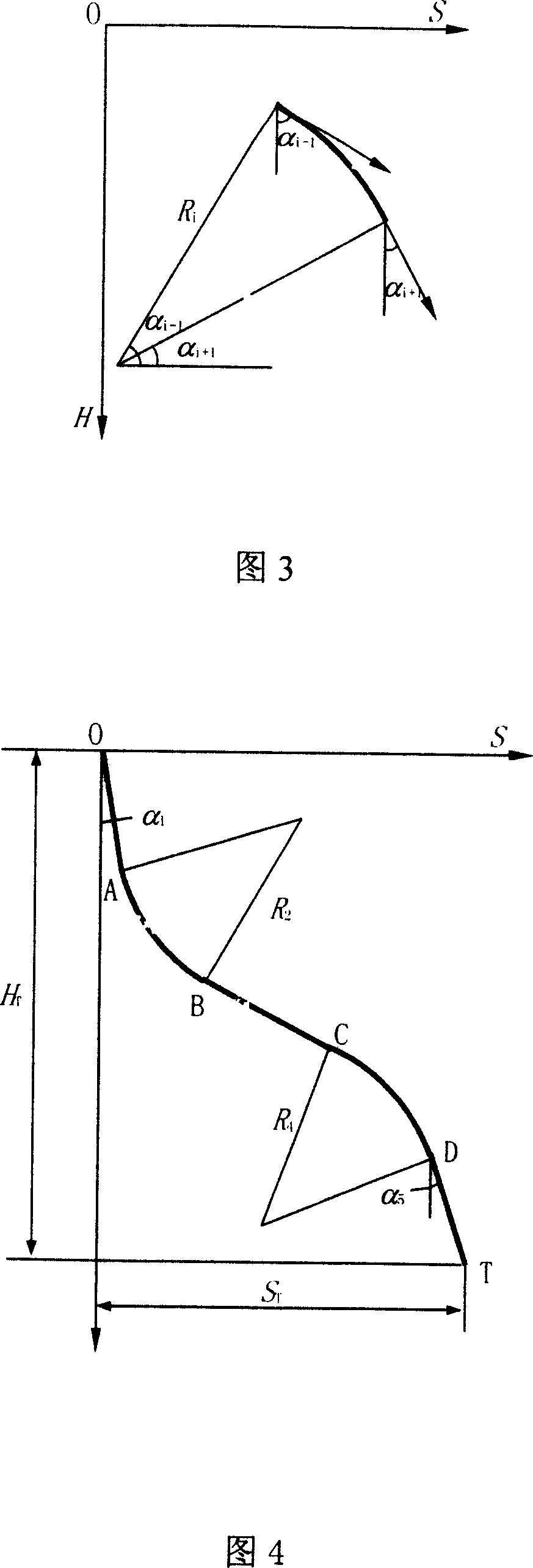
[0155] A directional well is designed with a vertical depth of 1500m and a horizontal displacement of 600m, and adopts an S-shaped well profile (a total of 5 well sections), as shown in Figure 4. The length of the first stabilizing section is 500m, and the inclination angle is 15°. is 150m, and the inclination angle is 8°.
[0156] Taking the well inclination angle α of the third well section (that is, the second stabilizing section) 3 , the curvature κ of the 4th well section (that is, the descending section) 4 , a total of two characteristic parameters are unknown variables.
[0157] Then get according to the design method of the present invention: the well inclination angle α of the 2nd stabilizing section 3 =38.495°, the curvature κ of the descending slope 4 =-6.132° / 100m. The design results are shown in Table 2.
[0158] Table 2 Design results of S-type directional wells
[0159]
Embodiment 2
[0160] Example 2: Three-increase horizontal well design
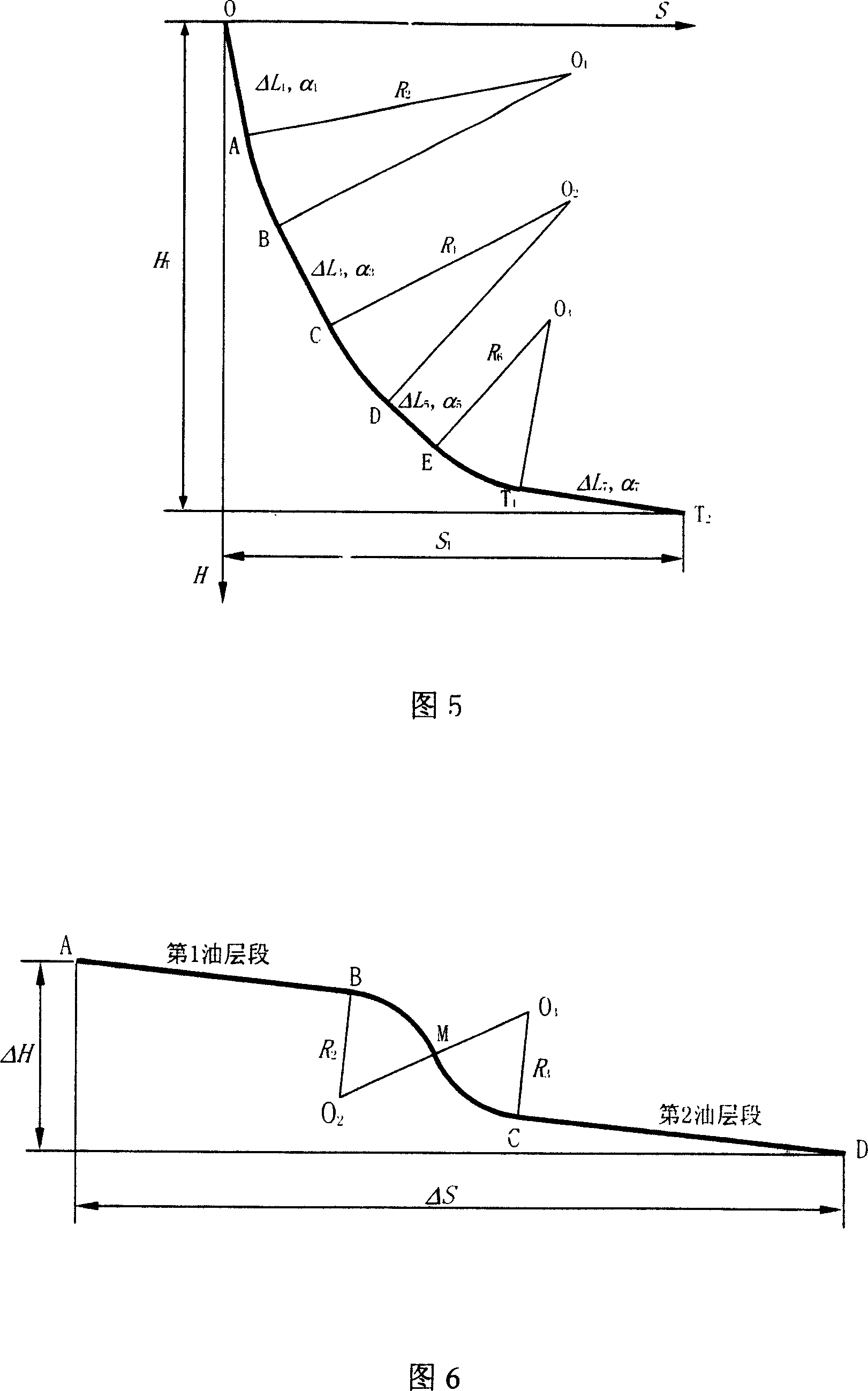
[0161] A horizontal well is designed with a vertical depth of 2000m, a displacement in front of the target of 630m, a horizontal section length of 500m, and a well inclination angle of 90°. A triple-increased well profile (7 sections in total) is used, as shown in Figure 5. The initial inclination angle is 0°, and the build-up point is 1450m; the inclination rate of the three inclination sections is 8° / 30m, 2° / 30m, and 10° / 30m, respectively, so that the inclination angle reaches 40° and 65° respectively , 90°.
[0162] Take the length ΔL of the third well section (that is, the second stabilizing section) 3 , the length ΔL of the 5th well section (namely the 3rd stabilizing section) 5 , a total of two characteristic parameters are unknown variables.
[0163] Then get according to the design method of the present invention: the length of 2 stabilizing sections is respectively 151.145m and 126.649m. The design results ...
Embodiment 3
[0166] Example 3: Ladder-shaped horizontal well section design
[0167]One horizontal well is used to develop two thin oil layers at different depths, and a stepped horizontal well section (total of 4 well sections) is used, as shown in Fig. 6. The geological design gives: the inclination angles of the two well sections in the oil layers are 88° and 90° respectively, the vertical depth difference of the target area is 10m, and the horizontal displacement is 420m. If the lower ladder track design scheme is adopted, build-up rates of -3° / 30m and 4.5° / 30m are selected for the two arc sections respectively, and the length of the second oil layer well section is required to be 150m.
[0168] Take the length ΔL of the first well section (that is, the first oil layer well section) 1 , the termination well inclination angle α of the second well section (that is, the descending section) 2 (that is, the α of point M in Figure 6 M ), a total of two characteristic parameters are unknow...
PUM
| Property | Measurement | Unit |
|---|---|---|
| Length | aaaaa | aaaaa |
Abstract
Description
Claims
Application Information