

Detection apparatus for cable assembly radio-frequency leakage and detection method
A cable assembly and testing device technology, which is applied in the field of testing devices for radio frequency leakage of cable assemblies, and can solve problems such as being difficult to implement.
- Summary
- Abstract
- Description
- Claims
- Application Information
AI Technical Summary
Problems solved by technology
Method used
Image

Examples
Embodiment Construction
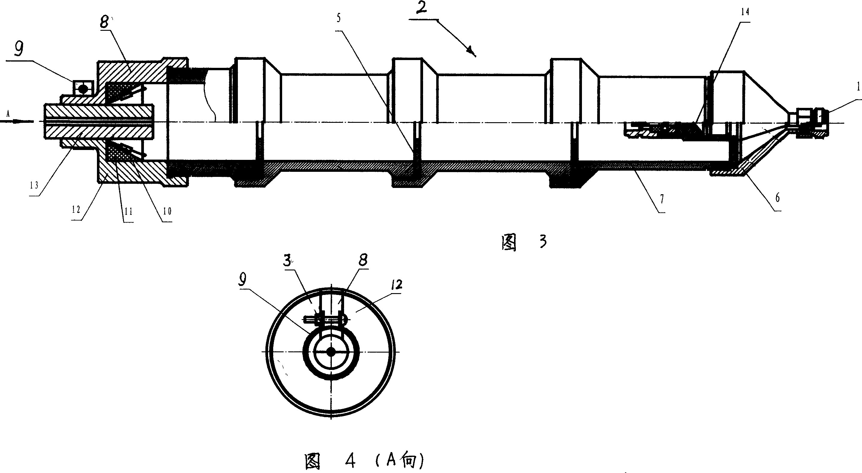
[0034] As shown in Figures 3 and 4, the test device of the present invention is mainly embodied in a radio frequency leakage signal collector 2 connected in series between the step attenuator and the microwave receiver, and this collector 2 has a cylindrical shell 7 , the two ends of the shell 7 are respectively closed by the end cover 12 and the front cover 6, and the matching load 14 with a voltage standing wave ratio less than 1.05 is connected in the front cover 6, and the matching load 14 extends into the shell 7; the inside of the end cover 12 An annular absorbing load 11 with an inner cone surface is installed, and six resistors 10 are arranged at intervals on the inner cone surface of the absorbing load 11 , and both ends of each resistor 10 are welded or glued on the end cap 12 . A test port 1 for signal output is fixed on the front cover 6 . Said shell 7 can be one section, and can also be multi-section threaded to meet the different lengths of the tested cable assem...
PUM
 Abstract
Description
Claims
Application Information