Disc molding die, mirror-surface plate and molded object

A technology of mirror panels and metal molds, which is applied in the field of mirror panels and molded products, metal molds for disc forming, to achieve the effect of shortening the forming cycle and preventing deformation

Inactive Publication Date: 2007-03-28
SUMITOMO HEAVY IND LTD +1
View PDF1 Cites 2 Cited by
  • Summary
  • Abstract
  • Description
  • Claims
  • Application Information

AI Technical Summary

Problems solved by technology

[0019] The present invention solves the above-mentioned problems of the conventional disk molding dies, and aims to provide a disk molding die, a mirror plate, and a mold that can uniformly cool the molded product and prevent printing unevenness in the printed area of ​​the molded product. Formed product

Method used


Image

  • Disc molding die, mirror-surface plate and molded object
  • Disc molding die, mirror-surface plate and molded object
  • Disc molding die, mirror-surface plate and molded object

Examples


Embodiment Construction

[0042] Embodiments of the present invention will be described in detail below with reference to the drawings.

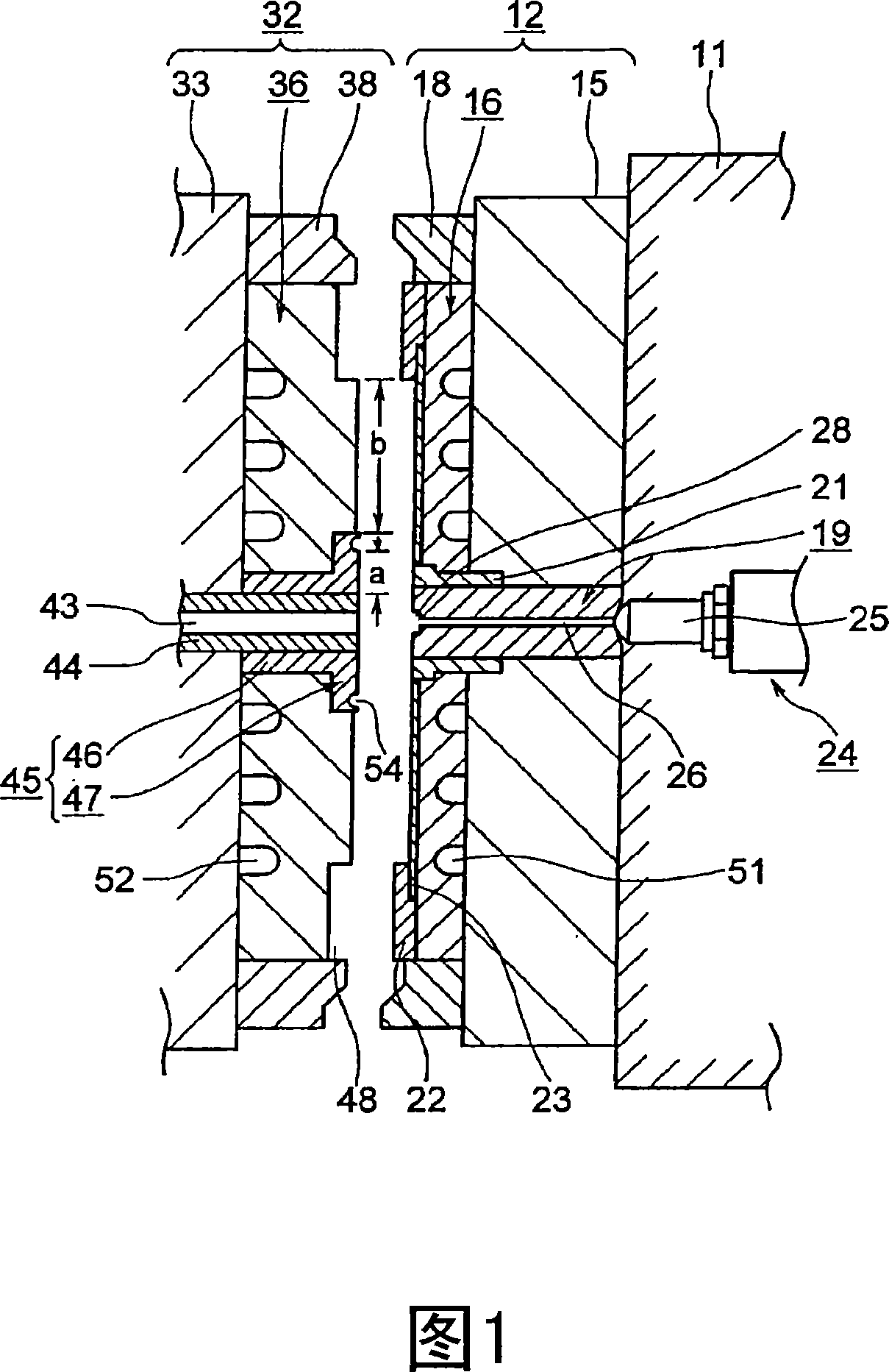
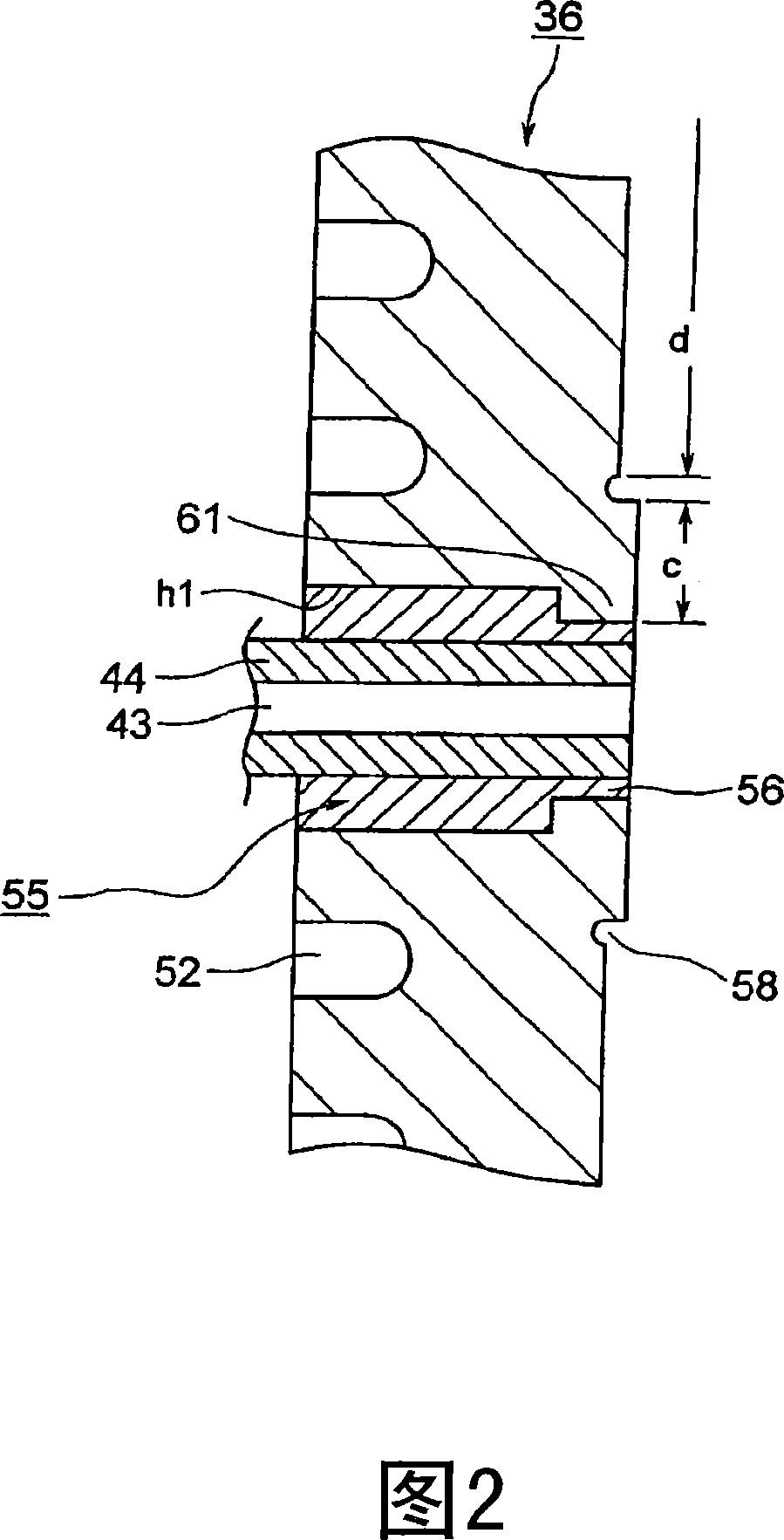
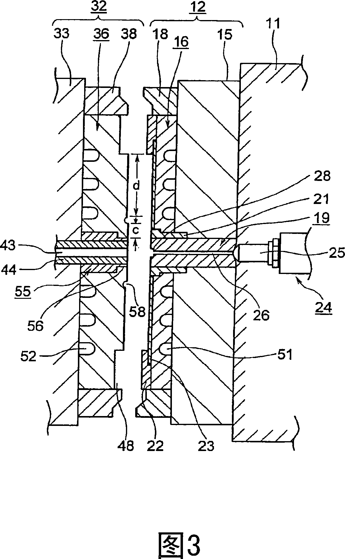
[0043] 2 is a cross-sectional view showing a main part of a disk-forming mold according to the first embodiment of the present invention, and FIG. 3 is a cross-sectional view of the disk-forming mold according to the first embodiment of the present invention.

[0044] In the figure, 11 is a fixed platen as a first support member, 12 is a metal mold assembly mounted on the fixed side of the fixed platen 11, and 32 is a movable plate not shown as a second support member. The mold assembly on the movable side of the platen is constituted by the mold assemblies 12 and 32 described above to form a disk forming mold. In addition, when describing the metal mold for forming a disk, on the side of the mold assembly 12 described above, the side close to the cavity space (not shown) formed between the mold assemblies 12 and 32 will be Let it be the front, and let the side away...


PUM


Abstract

A disc molding die, which can uniformly cool a molding object and does not generate printing nonuniformity in a printing area of the molding object, and a molded object are provided. The disc molding die is provided with a first die plate, a first mirror-surface plate, a second die plate arranged to freely advance and retreat to and from the first die plate, a second mirror-surface plate for forming a cavity with the first mirror-surface plate in a clamping state, a stamper (32), which is attached to one of the first and the second mirror-surface plates and has a fine pattern formed on its front edge plane, and a bush (55) arranged by penetrating the other of the first and the second mirror-surface plates. On a front edge plane of the above mentioned the other mirror-surface plate, the bush (55) is arranged inner than an area for forming a clamp area in a diameter direction. In this case, since an area of a front edge plane of the bush (55) becomes small, molding object cooling performance is prevented from deteriorating.

Description

technical field [0001] The present invention relates to a metal mold for forming a disk, a mirror panel and a molded product. Background technique [0002] Conventionally, in an injection molding machine for molding a disc substrate as a molded product, resin melted in a heating cylinder is filled into a cavity space in a disc molding die (for example, refer to Patent Document 1). [0003] Fig. 1 is a cross-sectional view of a conventional disk-forming die. [0004] In the figure, 11 is a fixed platen, 12 is a fixed-side mold assembly mounted on the fixed platen 11, and 32 is a movable-side mold assembly mounted on a movable platen (not shown). , the metal mold for forming a disk is constituted by the above-mentioned mold assembly 12,32. In addition, when describing the metal mold for forming a disk, on the side of the above-mentioned metal mold assembly 12, the side close to the cavity space (not shown) formed between the metal mold assembly 12 and 32 is set as Let it be...

Claims


Application Information

Patent Timeline
Patent Type & Authority Applications(China)
IPC IPC(8): B29C45/26B29C45/36G11B7/26G11B7/24047
CPCG11B7/263B29C2045/2661B29L2017/005B29C2045/2667B29C45/263B29C45/36G11B7/26
Inventor 渋谷裕二后藤义行稻田雄一泽石裕之
Owner SUMITOMO HEAVY IND LTD
Why Eureka
Try Eureka