

Heat exchanger
A heat exchanger and heat exchange tube technology, which is applied to heat exchange equipment, indirect heat exchangers, heat exchanger shells, etc. Heat Exchange Efficiency, Improved Heat Exchange Efficiency, Effect of Quantity Reduction
- Summary
- Abstract
- Description
- Claims
- Application Information
AI Technical Summary
Problems solved by technology
Method used
Image

Examples
Embodiment Construction
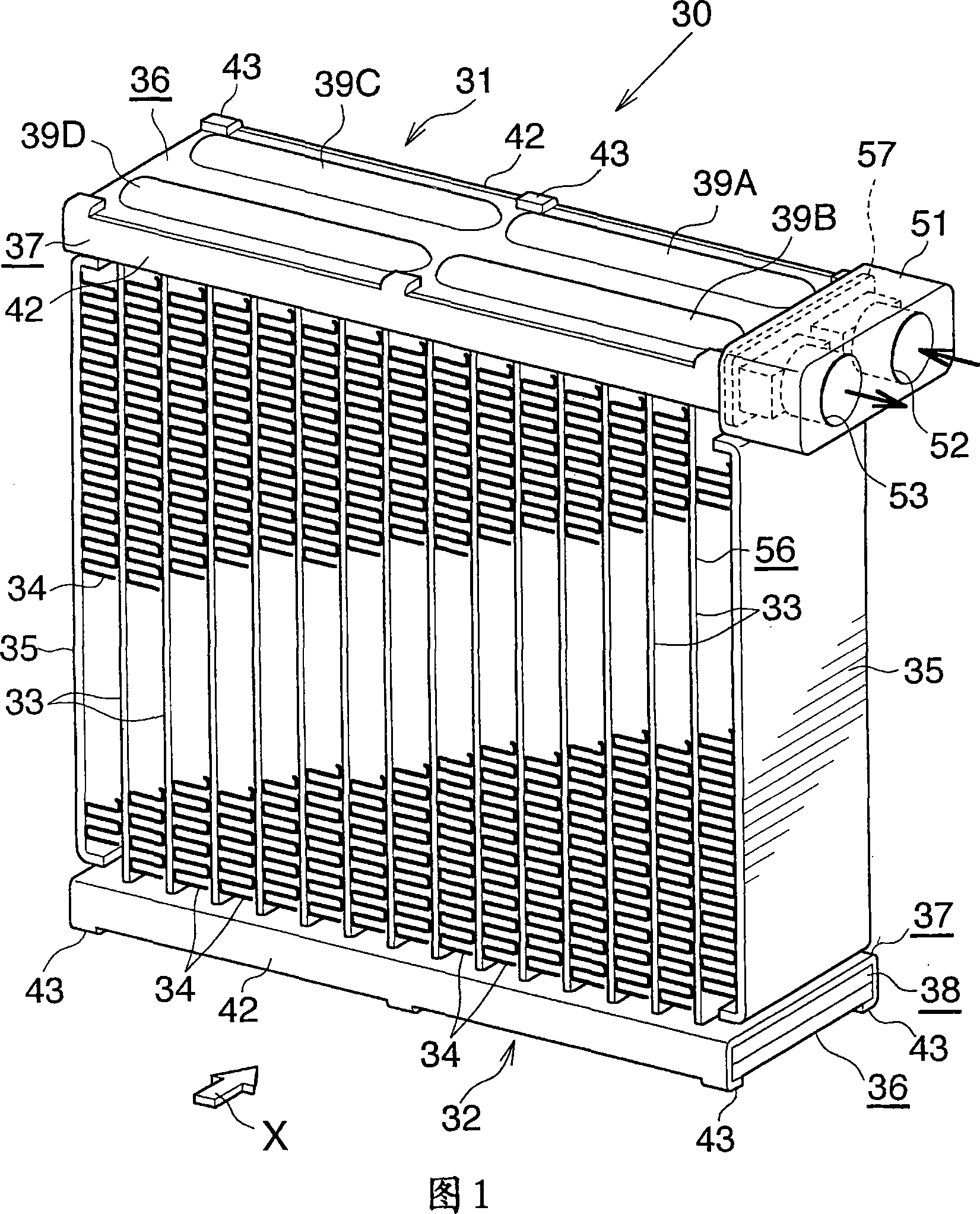
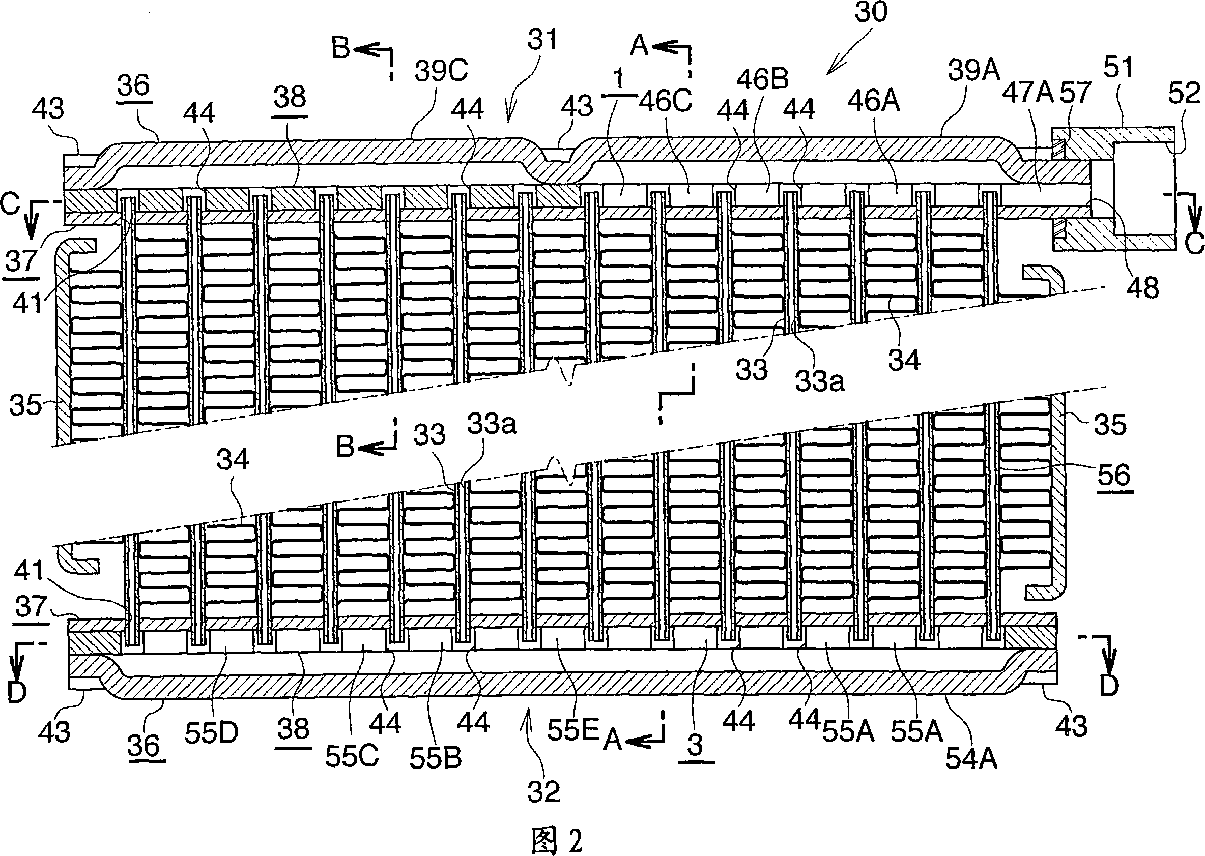
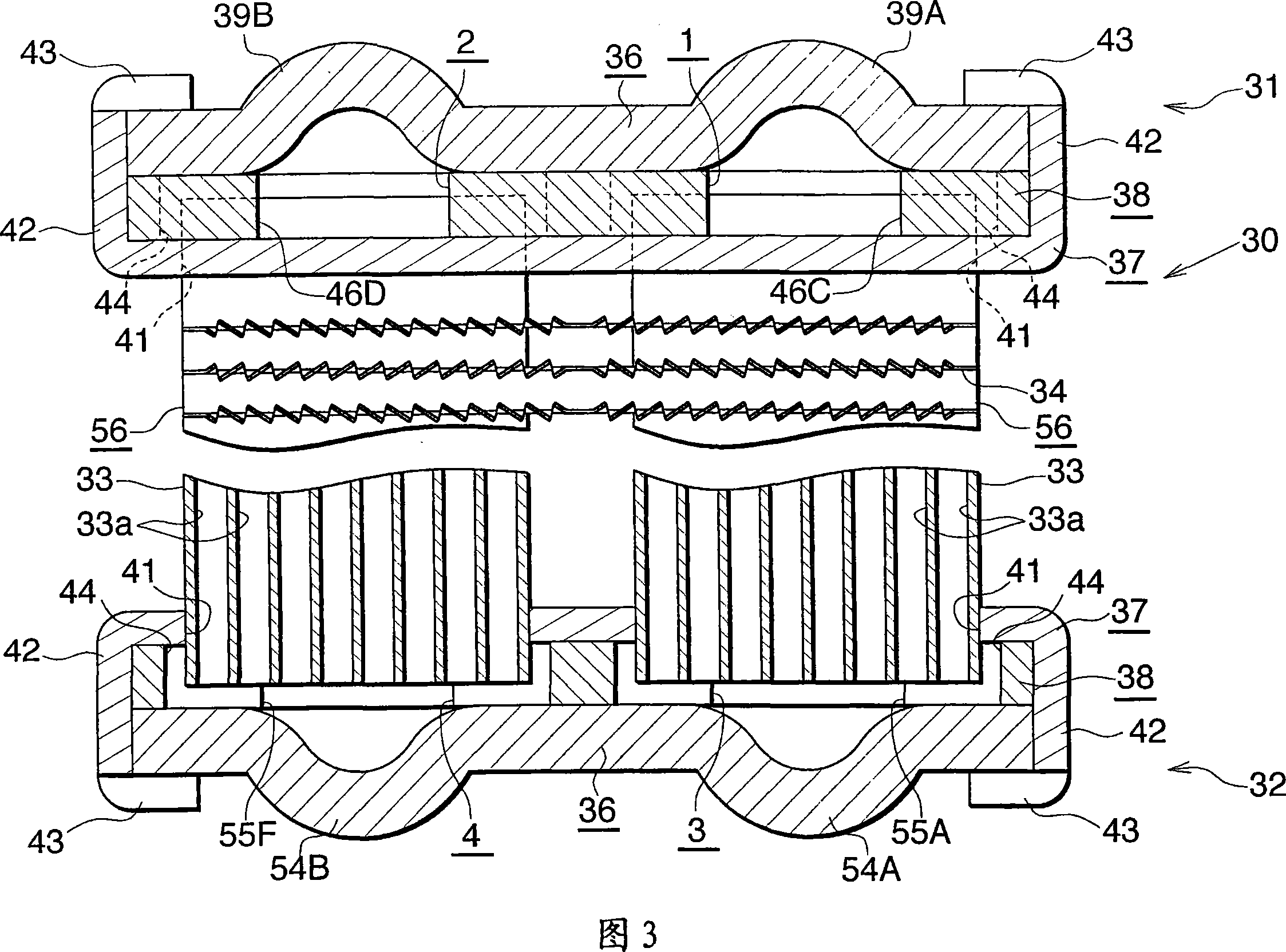
[0046] Embodiments of the present invention will be described below with reference to the drawings. This embodiment is a heat exchanger of the present invention suitable for use as an evaporator of a supercritical refrigeration cycle.
[0047] 1 to 3 show the overall configuration of an evaporator embodying the present invention, FIGS. 4 to 9 show the configuration of a main part of the evaporator, and FIG. 10 shows the flow of refrigerant passing through the evaporator of FIG. 1 .
[0048] In the following description, upper, lower, left-hand and right-hand sides in FIGS. 1 and 2 will be referred to as "upper", "lower", "left" and "right", respectively. In addition, the downstream side of the airflow passing through the airflow gap between each adjacent pair of heat exchange tubes (the direction indicated by the arrow X in Figures 1 and 10) will be referred to as "front", and the opposite side will be referred to as "rear". ".
[0049] Referring to Figures 1 to 3, for where...
PUM
 Abstract
Description
Claims
Application Information