
Device for monitoring the level of a container

A technology of liquid level and liquid storage, which is applied in the field of liquid level devices of liquid storage, and can solve problems such as device failure, magnet rupture, and prolapse

Inactive Publication Date: 2007-03-28
大陆-特韦斯捷克有限责任公司 +1
View PDF1 Cites 7 Cited by
  • Summary
  • Abstract
  • Description
  • Claims
  • Application Information

AI Technical Summary

Problems solved by technology

[0004] The disadvantage is that the magnets can break if damaged during manufacture or installation and can come out of the buoy
This can cause the buoy to stick and the device to fail

Method used


Image

  • Device for monitoring the level of a container
  • Device for monitoring the level of a container

Examples


Embodiment Construction

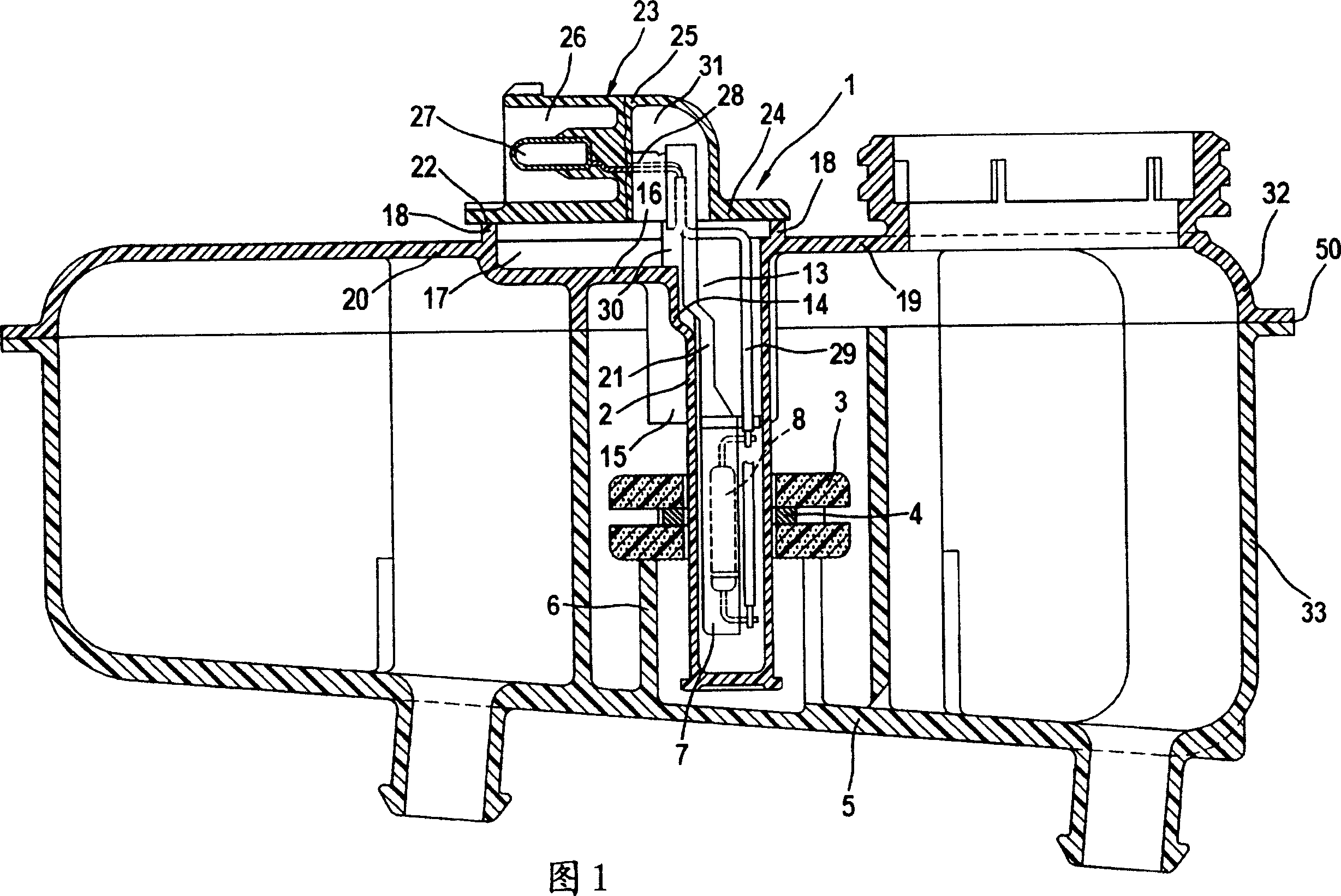
[0018] Figure 1 shows a reservoir 1 for hydraulic fluid, especially brake fluid, comprising a device for monitoring the liquid level of a container known from DE3716135A1. The accumulator 1 is fixed, for example, to the master cylinder (not shown) of the brake device of a motor vehicle, and is connected to a conduit 2 which extends into the accumulator and is closed at its end facing the inside of the accumulator, making The buoy 3, for example in a ring shape, is movably mounted along a duct 2 which preferably has a circular cross-section. The buoy 3 has a ring magnet 4. A tubular sleeve 6 protruding from the bottom 5 of the reservoir 1 and partially enclosing the duct 2 concentrically serves as a stop for the buoy 3. The stop limits the lowest position of the buoy 3 in the reservoir 1 and prevents the buoy 3 from leaving the duct 2.

[0019] A bracket 7 is provided in the catheter 2, and a reed switch 8 is fixed on the bracket. A terminal piece (Fahne) 21 is connected to the bra...


PUM


Abstract

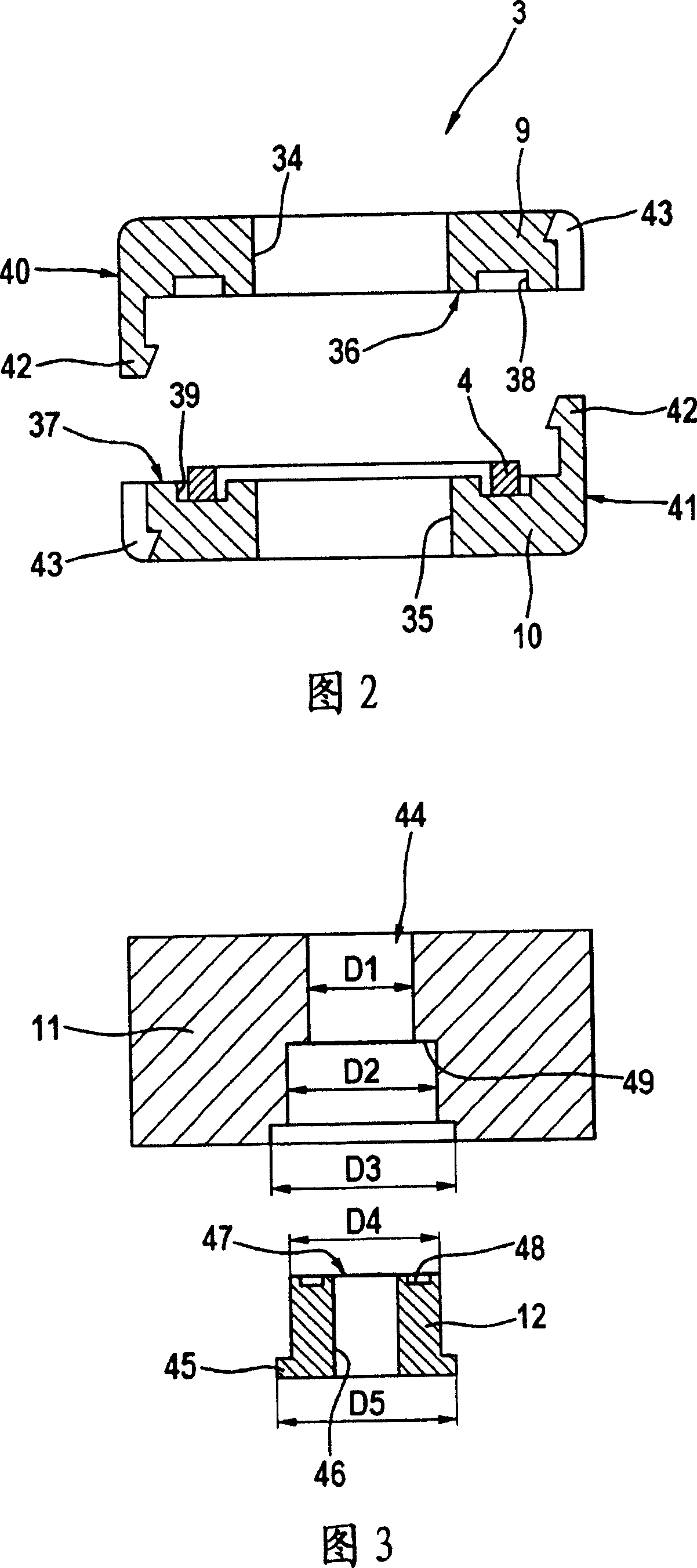
The invention relates to a device for monitoring the level of a container of a compensation tank (1), more particularly a hydraulic motor vehicle braking system, comprising a float (3) that has a magnet (4) for actuating a switch (8) or a sensor. The invention is characterized in that the float (3) consists of several parts, namely a first float part (9, 11) and a second float part (10, 12) and the magnet (4) is encased between both float parts (9, 10, 11, 12).

Description

Technical field [0001] The present invention relates to a device for monitoring the liquid level of a reservoir, especially a hydraulic brake device of a motor vehicle, the device comprising a buoy with a magnet for actuating a switch or a sensor. Background technique [0002] In the hydraulic brake device of a motor vehicle, the required brake fluid is contained in the reservoir, and the liquid level of the container is monitored by a magnet for turning on the switch contacts. If the level of brake fluid drops, the switch contacts are turned on. This signal is processed in an electronic controller and can alert the motor vehicle driver through indicator lights and the like. At this time, it must be ensured that the reservoir is always filled with a minimum amount of brake fluid so as not to affect the operation of the brake device. A container liquid level monitoring device is usually used, in which, when the container liquid level is lower than a defined minimum value, once the...

Claims


Application Information

Patent Timeline
Patent Type & Authority Applications(China)
IPC IPC(8): H01H36/02G01F23/76B60T17/22
Inventor P·坦德勒S·京特T·耶保塞克J·沃尔特
Owner 大陆-特韦斯捷克有限责任公司
Learn More