

Electric cooker
A technology of electric rice cooker and surface area, which is applied in the direction of special materials for cooking utensils, heating devices, cooking utensils, etc., and can solve the problem of high price of heat-resistant materials
- Summary
- Abstract
- Description
- Claims
- Application Information
AI Technical Summary
Problems solved by technology
Method used
Image

Examples
Embodiment Construction
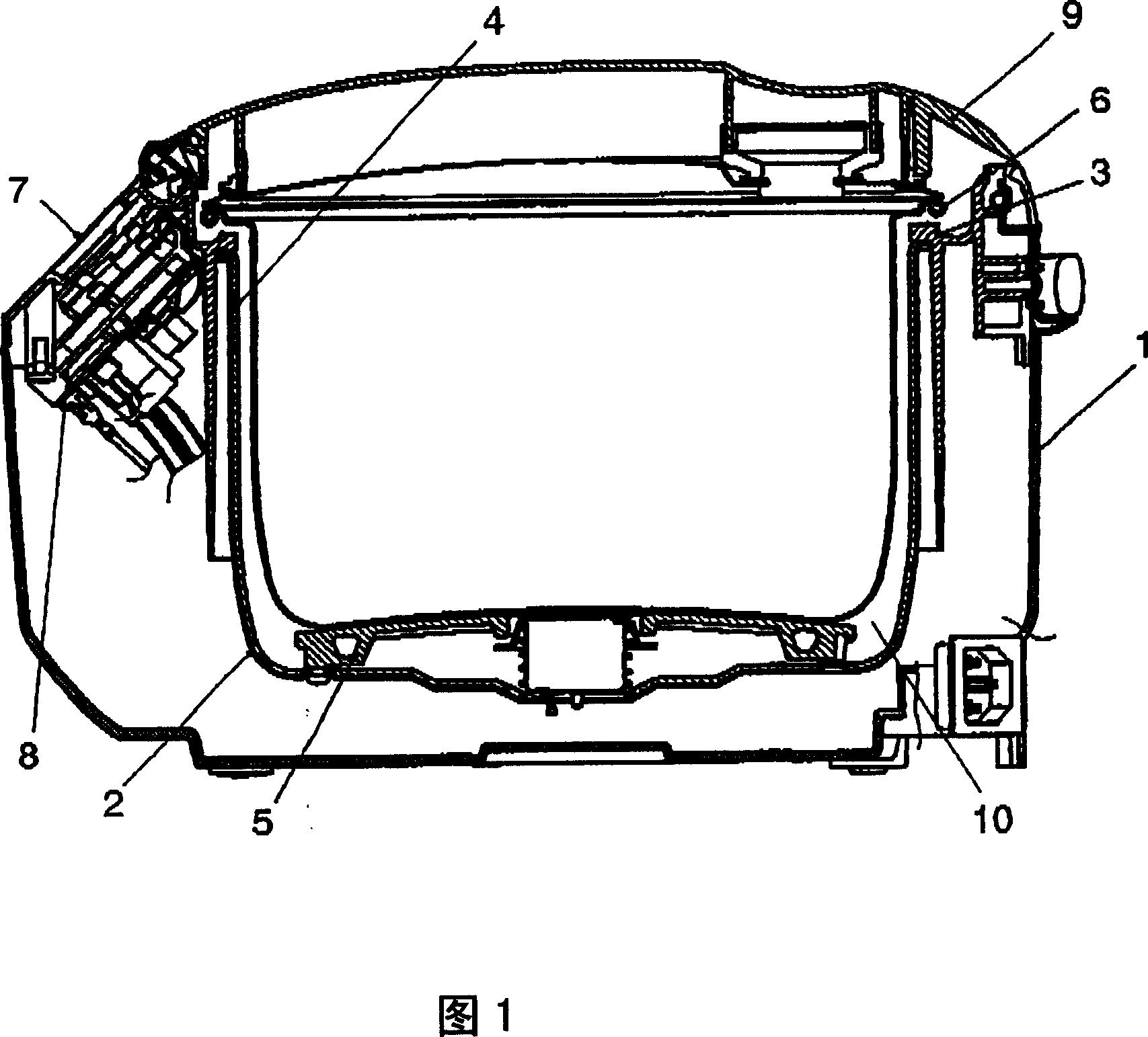
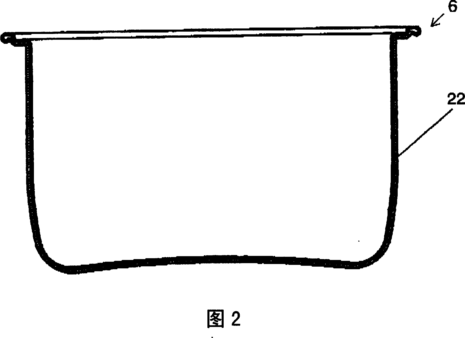
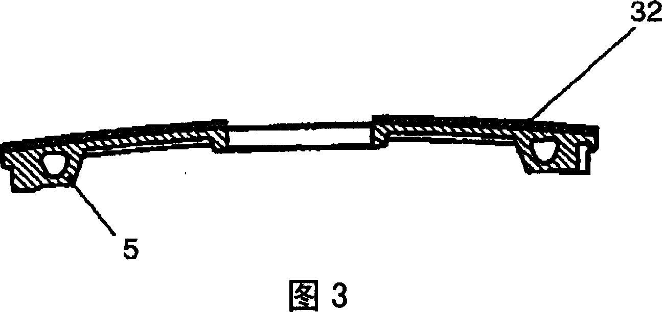
[0014] Fig. 1 is a longitudinal sectional view of an electric rice cooker according to an embodiment of the present invention. The main body 1 has a substantially cylindrical bottomed shape with an open upper surface. Inside the main body 1 , a substantially cylindrical bottomed protection frame 2 is disposed as a pan storage portion. The outer periphery of the upper end of the protective frame 2 is fixed to a plastic ring-shaped upper frame 3 disposed on the upper end of the main body 1 . A black layer 4 is provided on the inner periphery of the protective frame 2 by applying black heat-resistant aluminum using an inorganic heat-resistant dye or melamine paint. A casting heater (hereinafter, heater) 5 is fixed on the bottom inner surface of the protective frame 2 . The pot 6 is disposed in the protective frame 2 in a detachable manner by being placed on the heater 5 . The operation panel unit 7 is disposed on the upper front portion of the main body unit 1 . The controlle...
PUM
 Abstract
Description
Claims
Application Information