
Liquid heating vessels

A liquid heating container and heating container technology, applied in the direction of fluid heaters, water heaters, immersion heating devices, etc., can solve the problem that the device cannot be widely used, achieve the effect of coil size and cost, and increase safety

Active Publication Date: 2007-04-04
STRIX LTD
View PDF2 Cites 4 Cited by
  • Summary
  • Abstract
  • Description
  • Claims
  • Application Information

AI Technical Summary

Problems solved by technology

However, electronic controls are significantly more expensive than traditional mechanical controls that include complex logic circuits and require many expensive solid-state components
As a result such devices cannot be widely used in the market

Method used


Image

  • Liquid heating vessels
  • Liquid heating vessels
  • Liquid heating vessels

Examples


Embodiment Construction

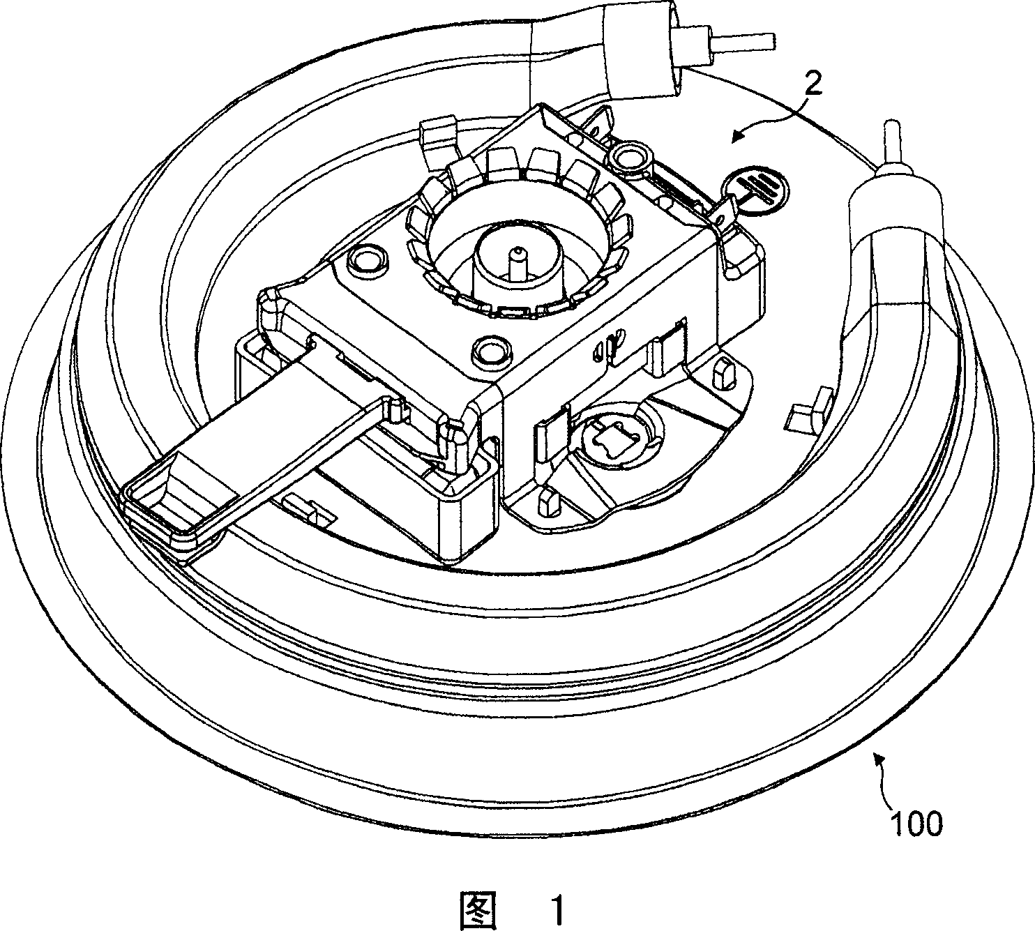
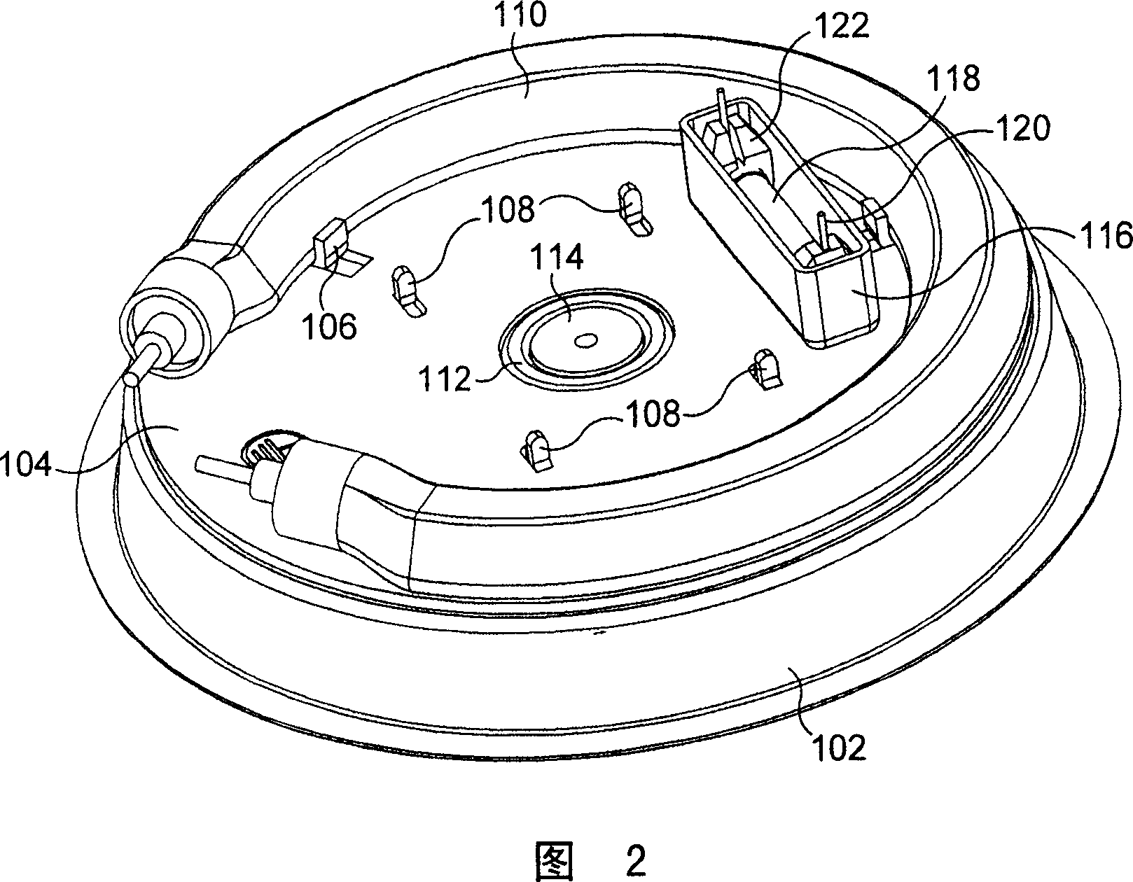
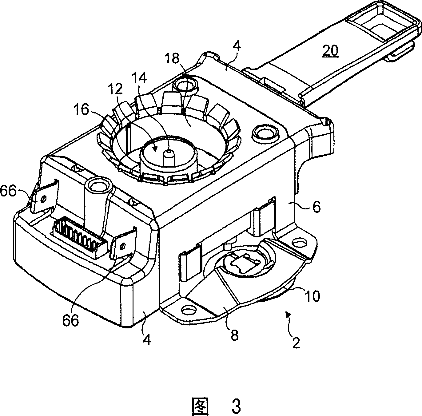
[0054] FIG. 1 shows the control element 2 of the heater 100 mounted under the floor, which is more clearly represented in FIG. 2 . The under-floor heater (flipped from the direction of its use for explanation) includes a dish-shaped stainless steel plate 102 mounted to close the opening in the base of the liquid heating vessel. Any convenient installation method can be used. For example, although not shown, the plate 102 may be provided with an upwardly open peripheral groove to enable it to be secured with Applicants' Sureseal securing system, more details of which can be found in WO 96 / 18331.

[0055] Brazed to the bottom of plate 102 is an aluminum heat spreader plate 104 . A number of joints 106 , 108 are separated from here: for providing a conventional housing heating element brazed to the diffuser plate 104 , respectively; and for connection with the control element 2 .

[0056] In the center of the stainless steel plate 102 is an annular wall 112 formed by a correspo...


PUM

PropertyMeasurementUnit
Thermal expansion coefficientaaaaaaaaaa

Abstract

A liquid heating vessel comprises heating means (110) for heating liquid in the vessel, electronic control means (80), electromagnetic switching means (60) for interrupting or reducing power to the heating means (110), and temperature sensing means (26) for providing a signal dependent on the temperature of liquid in the vessel to the control means (80). The control means (80) is arranged to operate the electromagnetic switching means (60) to interrupt or reduce power to the heating means (11) in response to the control means (80) determining that a pre-determined temperature condition has been reached.

Description

technical field [0001] The present invention relates to liquid heating vessels, but is not particularly limited to controlling vessels for heating water in various operating modes. Background technique [0002] It is well known to provide liquid heating vessels, such as brewing vessels with electronic controls that allow the user to select one of many possible modes of operation, such as heating to a temperature of 80-85°C suitable for coffee; heating to boil or hold Drink warm. These electronically controlled vessels can provide a wider range of possible functions than those available with conventional heat engine controlled vessels. However, electronic controls are significantly more expensive than traditional mechanical controls that include complex logic circuit diagrams and require many expensive solid-state components. As a result, such devices cannot be widely used in the market. SUMMARY OF THE INVENTION [0003] It is an object of the present invention to provid...

Claims


Application Information

Patent Timeline
IPC IPC(8): F24H1/18F24H9/20A47J27/21H05B1/02H05B3/82
CPCH05B1/0213H05B3/82A47J27/21066H05B1/0269A47J27/21058A47J27/21083
Inventor M·J·斯科特I·芬纳A·M·G·米克斯
Owner STRIX LTD
Learn More