Object-size measurement system and method

A measuring and dimensional technology, applied in the field of confocal microscopy devices, can solve the problems of weak signal and inability to reach the photodetector 15

Inactive Publication Date: 2007-04-04
IND TECH RES INST
View PDF4 Cites 16 Cited by
  • Summary
  • Abstract
  • Description
  • Claims
  • Application Information

AI Technical Summary

Problems solved by technology

When the object to be measured 16 moved in the axial direction as shown by the arrow, the surface of the object to be measured 16 would leave the focal plane of the first objective lens 12 (with reference to the object to be measured 16 shown in the thick dotted line in FIG. is the defocus plane), the light previously reflected by the object under test 16 (please refer to the thin dotted line in Fig. The signal output by device 15 is weak

Method used


Image

  • Object-size measurement system and method
  • Object-size measurement system and method
  • Object-size measurement system and method

Examples


Embodiment Construction

[0055] The aforementioned purpose or features of the present invention will be described in detail according to the accompanying drawings, but it should be understood that the accompanying drawings and the examples given are only for illustration rather than limiting or narrowing the present invention.

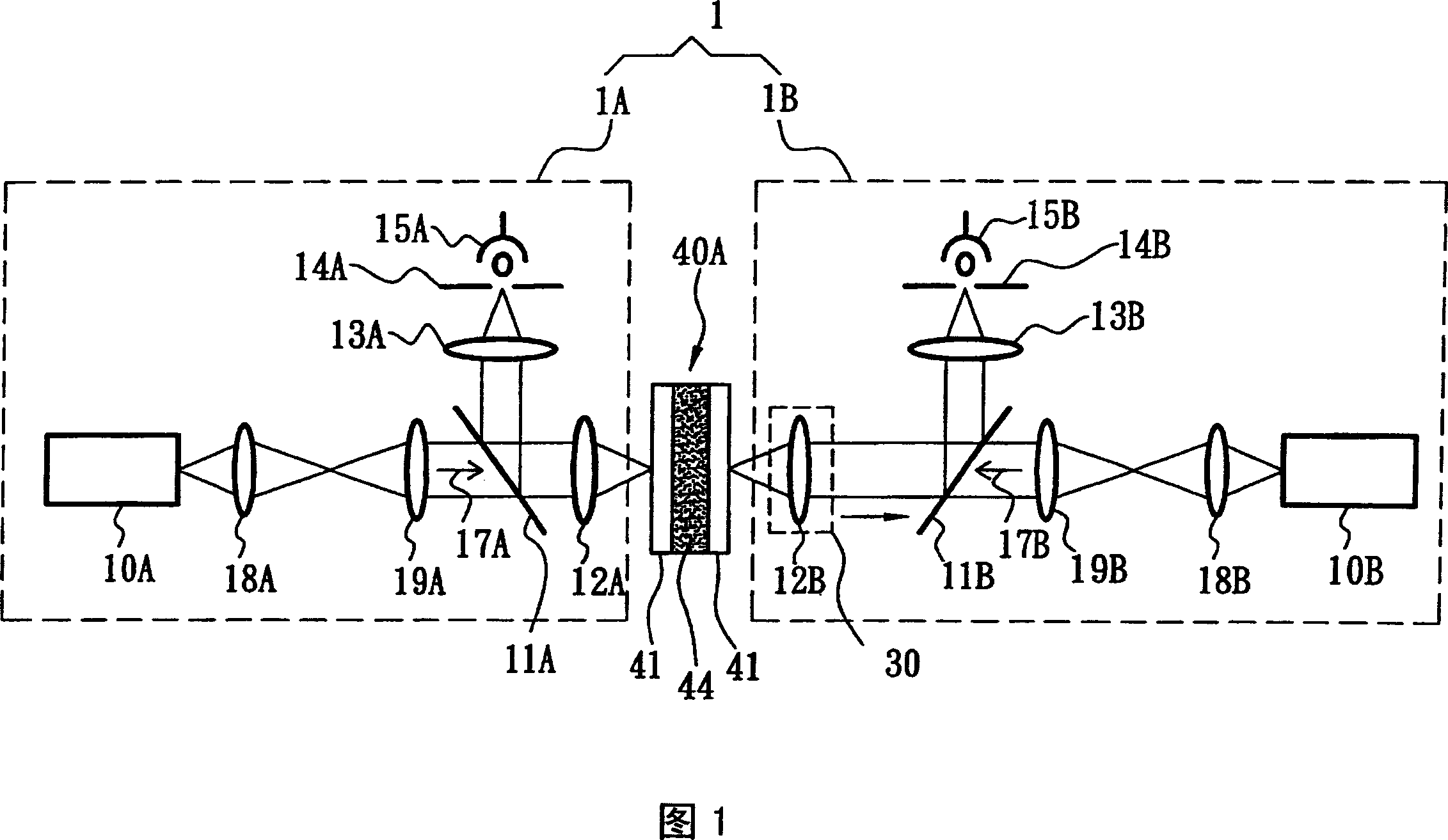
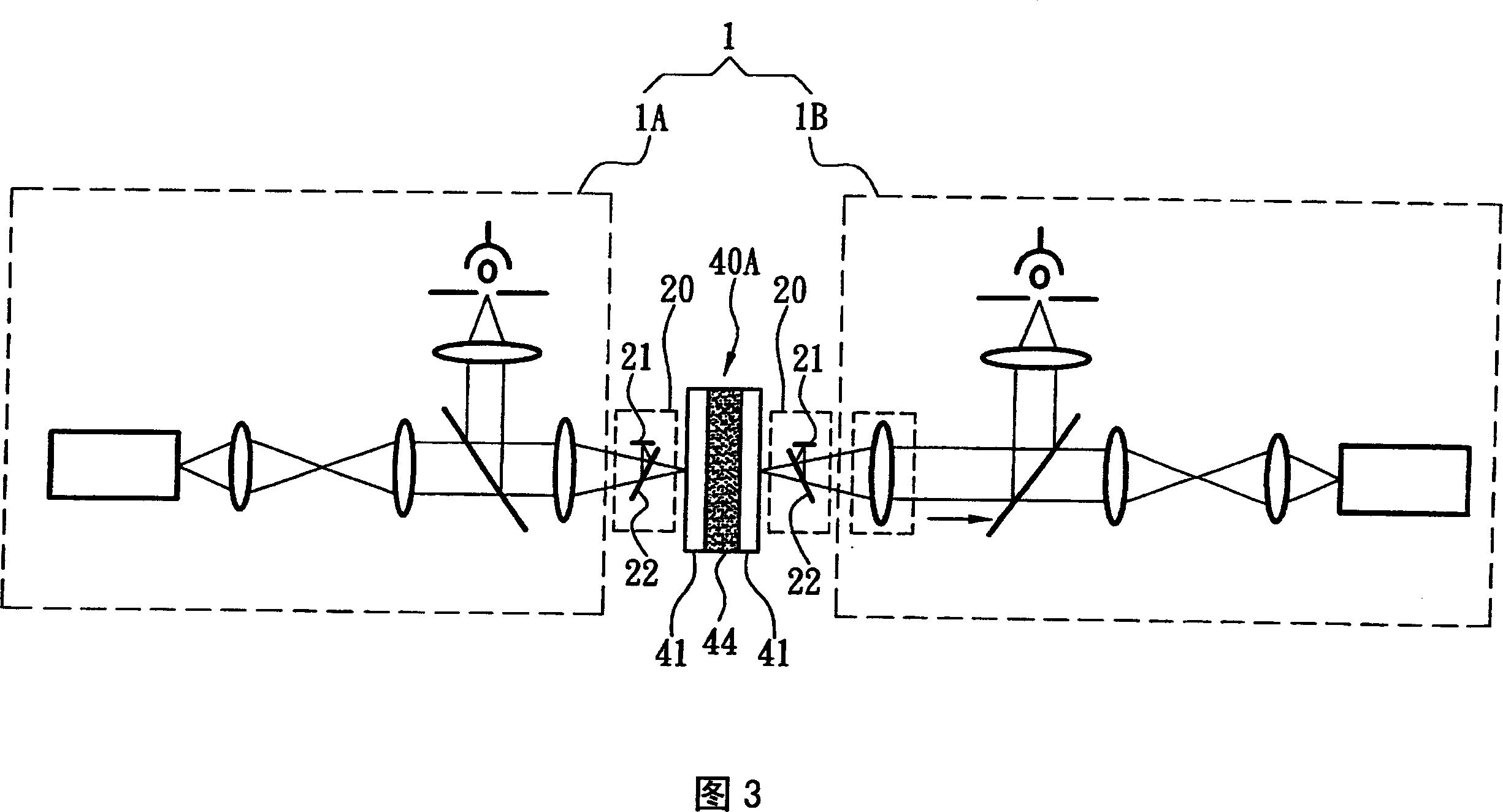
[0056] As shown in Figure 1, the object size measurement system 1 of the present invention includes a first confocal microscopic measurement device 1A, a second confocal microscopic measurement device 1B and a displacement device 30, the first confocal microscopic measurement device 1A and the second confocal microscopic measurement device 1A The confocal microscopic measurement device 1B is respectively arranged on the first and second side end surfaces of the thickness direction of the object to be measured (such as liquid crystal) 40A in a mirroring manner, and each device has a light source 10, a beam splitter as shown in FIG. 11. The structure of the known conventional con...


PUM


Abstract

A system used for measuring size of article is featured as distributing the first and the second confocal microscopic measurement device at end surfaces of the first and the second sides on direction of article size to be measured and setting the first objectives of two confocal microscopic measurement devices to face separately to two end surfaces of article to be measured then carrying and setting the first objective of the second confocal microscopic measurement device on displacement unit for getting near to or far from measured article end surface being faced by said objective in following with axial movement of said displacement unit.

Description

technical field [0001] The present invention relates to an object size measurement system, especially a measurement system in which confocal microscopic devices are respectively arranged on both ends of the thickness of the object to be measured (such as liquid crystal) to measure the thickness of the object to be measured; and A measurement method applied to the aforementioned system. Background technique [0002] The display quality of a liquid crystal display (LCD) is affected by the following three parameters: display color, response speed and orientation stability, while the thickness of the liquid crystal layer (cell gap) is It is an important factor affecting the above three parameters. [0003] The thickness of the liquid crystal layer is based on the assumption that the arrangement of the liquid crystal molecules in the slit is ideal in the traditional measurement framework, so that it meets the Mauguin's limit (Mauguin's limit), but in fact this is one of the main...

Claims


Application Information

Patent Timeline
Patent Type & Authority Applications(China)
IPC IPC(8): G01B11/06G02F1/13
Inventor 郑凯宇陈彦良徐祥瀚陈怡菁蓝玉屏
Owner IND TECH RES INST
Why Eureka
Try Eureka