Combined continuous extruder cavity

An extrusion cavity and combined technology, which is applied in metal extrusion forming tools, metal extrusion, metal processing equipment, etc., can solve the problems of rising production costs, deformation of block materials, expensive materials, etc., and achieve economical manufacturing Material, height reduction effect

Active Publication Date: 2007-04-11
大连康丰科技有限公司
View PDF0 Cites 11 Cited by
  • Summary
  • Abstract
  • Description
  • Claims
  • Application Information

AI Technical Summary

Problems solved by technology

In the process of production and use, the cavity is a vulnerable part. Because the materials selected for the cavity are expensive and have a short lifespan, the production cost incr

Method used


Image

  • Combined continuous extruder cavity
  • Combined continuous extruder cavity
  • Combined continuous extruder cavity

Examples


Embodiment Construction

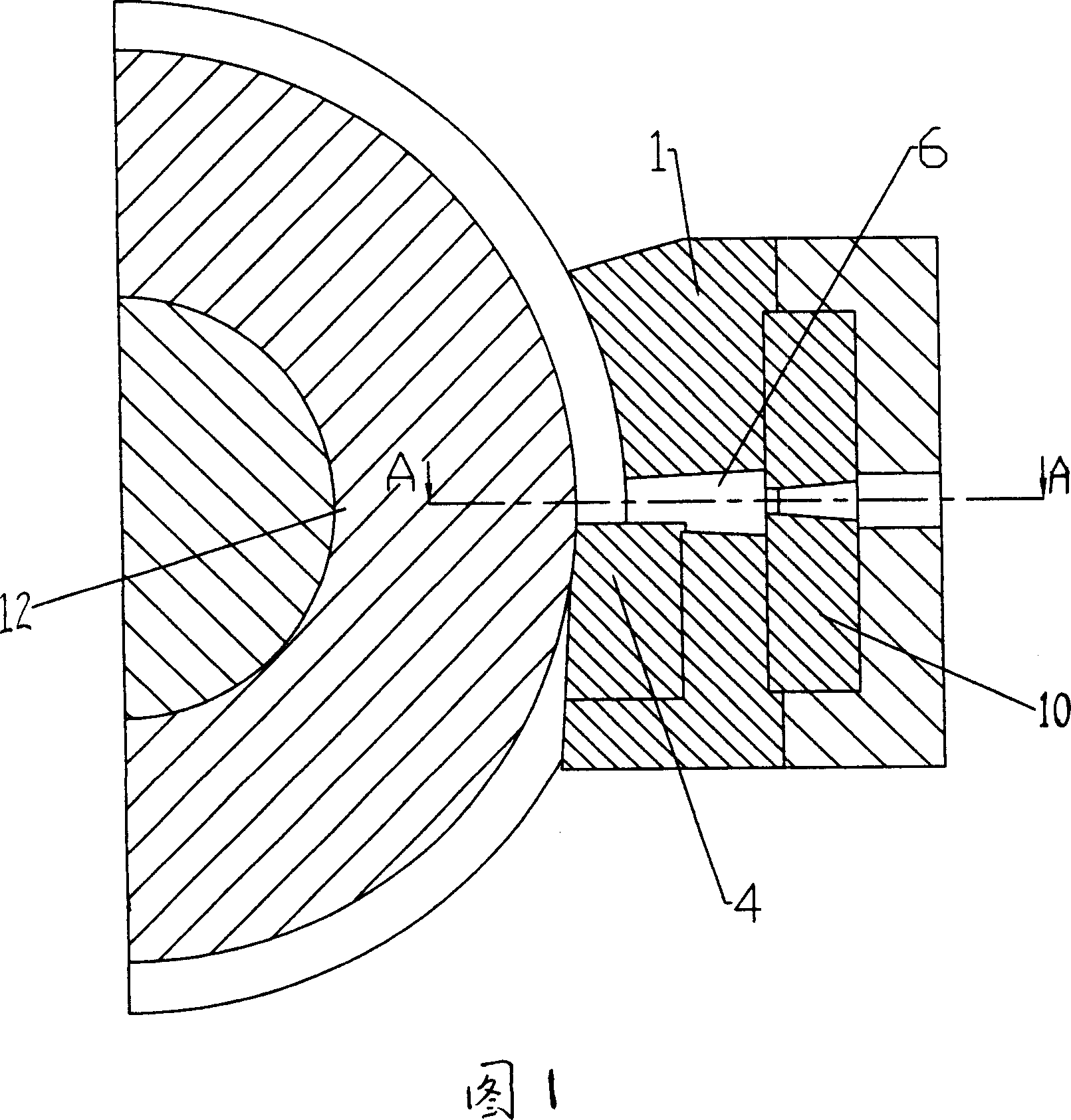
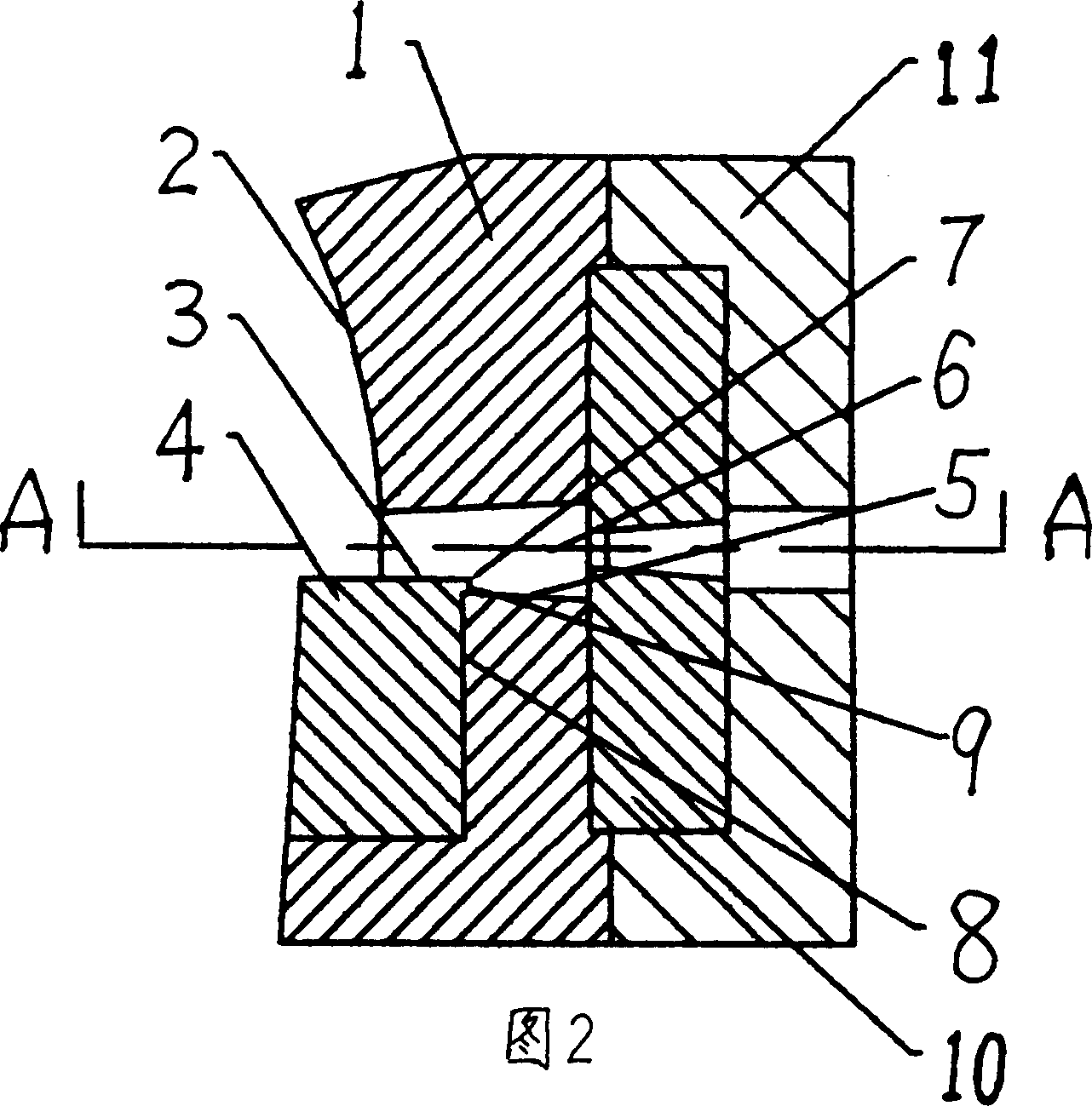
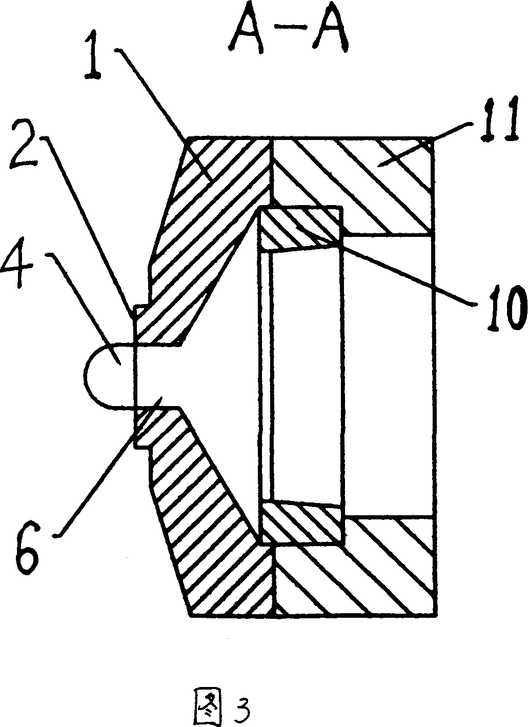
[0014] Extrusion equipment as shown in Figure 1, comprises extrusion wheel 12 and cavity, and cavity is shown in Figure 2, is made up of cavity panel, cavity bottom plate, stopper block and mould, includes seal on cavity panel 1 The surface 2, and the feed port 6, the stop block 4 and the cavity panel are split structures, the stop block is mounted on the cavity panel, and can be disassembled, and the end face 3 of the feed port of the stop block 4 is higher than the entrance The feed port surface 5 can also be aligned with the feed port face 5, and there is a sealing boss 7 that goes deep into the cavity feed port 6 at the junction of the feed block 4 feed port surface and the cavity. The end surface 9 under the table covers the joint surface 8 formed between the blocking block 4 and the cavity panel 1, the blank metal flow channel of the cavity panel 1 is a trapezoidal flat channel, and the mold 10 is only partially installed in the cavity panel 1, The rest of the mold 10 fi...


PUM


Abstract

The present invention relates to shaped section extruding apparatus, and is especially one kind of combined continuous extruder cavity. The cavity consists of panel including sealing plane and feeding port, bottom plate, material stoppers as independent parts embedded to the cavity, and mold. The cavity in the combined structure with embedded material stoppers may have material stoppers of different material for greatly raised load bearing capacity and may have the damaged material stopper replaced without need of replacing the whole cavity. The cavity bottom plate is so designed that mold may be installed, and this can lower the height of the cavity obviously and saving material for the cavity.

Description

Technical field: [0001] The invention relates to equipment for manufacturing copper and aluminum busbars, ladder bars, copper flat wires, various bars and other nonferrous metal products by continuous extrusion. Background technique: [0002] The cavity of the existing continuous extruder is composed of several parts, such as a sealing surface, a material blocking block, a feed inlet, a billet flow channel, and a cavity for installing a mold, and these parts are a complete part. In the process of production and use, the cavity is a vulnerable part. Since the material selected for the cavity is expensive and has a short lifespan, the production cost increases. In most cases, the damage of the cavity is caused by deformation or cracking of the stopper, which causes damage to the entire cavity and needs to be replaced as a whole. Invention content: [0003] The purpose of the present invention is to overcome the above-mentioned disadvantages and provide a combined continuous...

Claims


Application Information

Patent Timeline
IPC IPC(8): B21C23/21B21C25/00
Inventor 刘元文宋宝韫
Owner 大连康丰科技有限公司
Why Eureka
Try Eureka