Small power cage type induction motor

A low-power, cage-type technology, applied in asynchronous induction motors, electric components, electromechanical devices, etc., can solve the problems of multi-material cost and suboptimal cooling effect

Inactive Publication Date: 2007-04-11
江门市金羚排气扇制造有限公司
View PDF0 Cites 12 Cited by
  • Summary
  • Abstract
  • Description
  • Claims
  • Application Information

AI Technical Summary

Problems solved by technology

The air cooling system of this design is actually applied to products, especially directly used for small power motors. The cooling effect is not ideal. When the temperature rise of the motor winding is too high, the electromagnetic design can only be modified, so as to increase more material costs.

Method used


Image

  • Small power cage type induction motor
  • Small power cage type induction motor
  • Small power cage type induction motor

Examples


Embodiment Construction

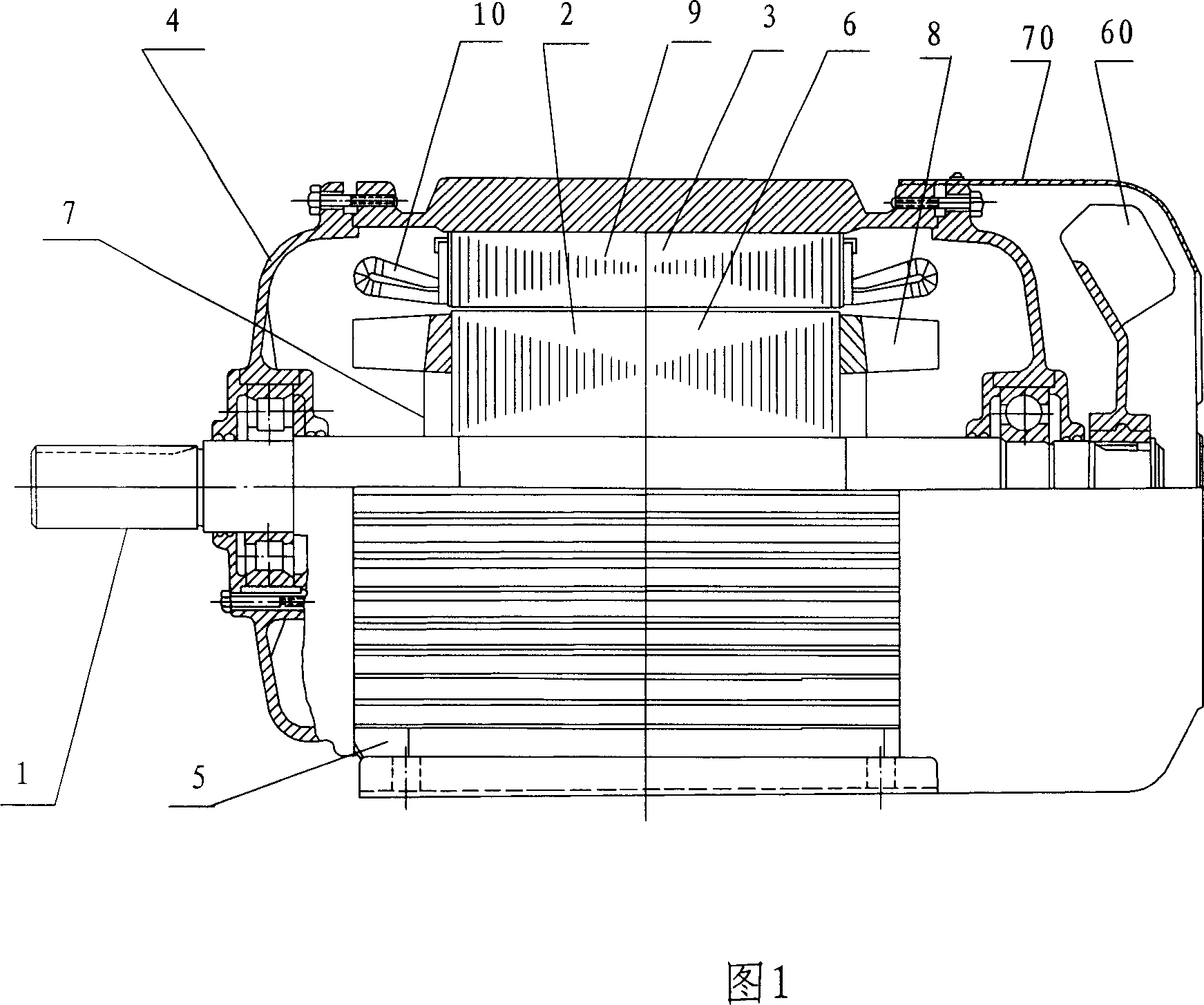
[0027] The motor of the embodiment of the present invention can be improved on the basis of the traditional design of the national industry standard Y series or AO2, BO2, CO2 and DO2 series motors, as shown in Figure 8-3 in the "Motor Design" mentioned in the background technology. The structure of a small cage induction motor is shown in Figure 1, including:

[0028] ——rotating shaft 1, rotor 2, stator 3, end cover 4, frame 5, outer fan 60 and windshield 70;

[0029] - The rotor 2 includes a rotor core 6 and a cast aluminum cage winding, the cage winding includes a conductive ring 7 and its inner fan blades 8 protruding axially;

[0030] - the stator 3 includes the stator core 9 and the stator windings;

[0031] - The end 10 of the stator winding radially surrounds the rotor inner fan blade 8 .

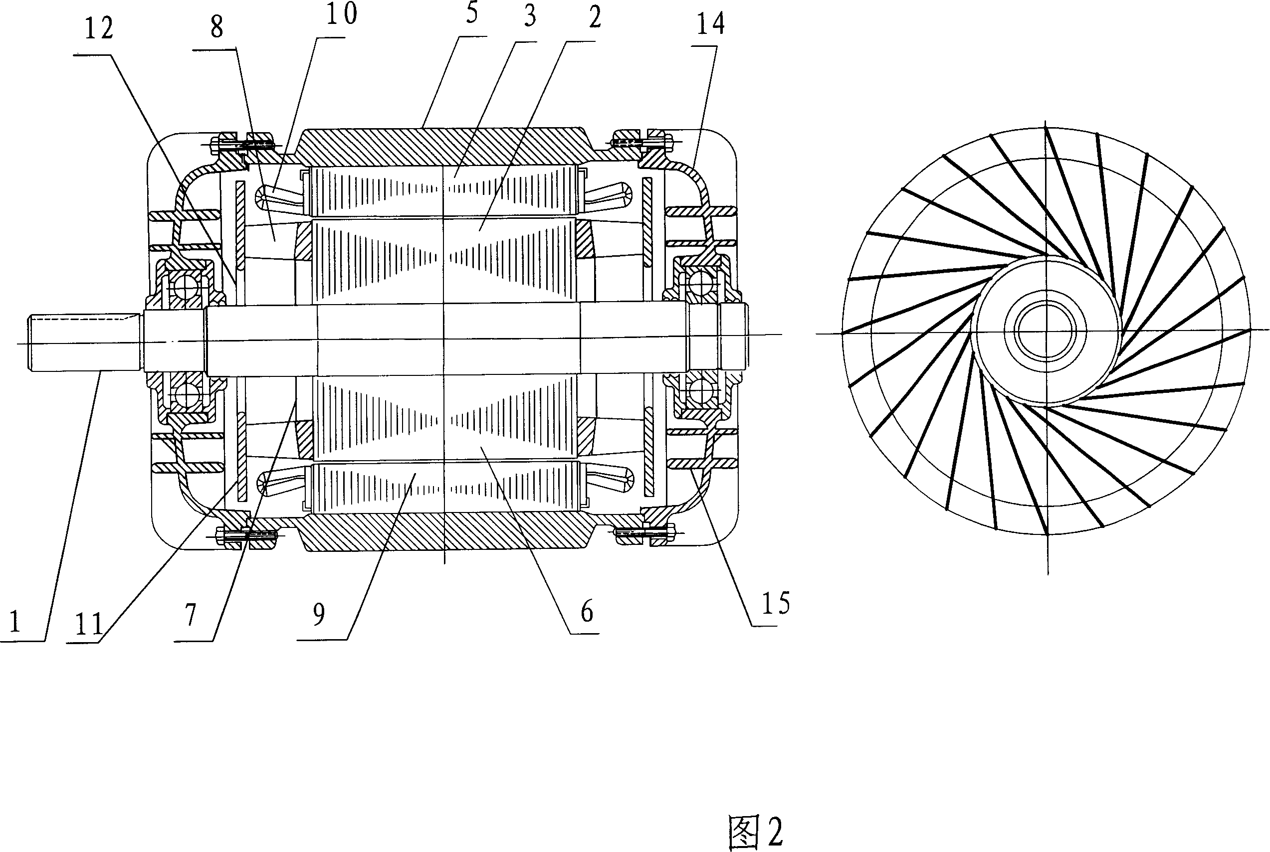
[0032] The structural diagram of the motor of the first embodiment of the present invention is shown in FIG. 2 . The motor is a modified design of the enclosed small and medium-si...


PUM


Abstract

This invention relates to a small power cage induced motor including a shaft, a rotor, a stator, an end cover and a base, in which, said rotor includes a rotor iron core and internal fan vanes extending outside axially from the end part, said stator includes a stator core and a winding, the end of which surrounds the vanes of the internal fan characterizing that the axial outer end of the vane is connected to a turning side surrounding said shaft.

Description

technical field [0001] The invention relates to a small-power cage-type induction motor, especially its cooling structure, which belongs to H02K9 / 06 in the International Patent Classification Table. Background technique [0002] Cage induction motors have a long history. The traditional design of closed or protected small and medium-sized cage induction motors can be found in "Motor Design" (Chen Shikun, Xi'an Jiaotong University, Mechanical Industry Press, Beijing 1st Edition, 1982), and its typical structure is shown in Figure 8-1 in P164-165 of this book 3 and Figure 8-4. The air cooling system of this design is actually applied to products, especially directly used for small power motors. The cooling effect is not ideal. When the temperature rise of the motor winding is too high, the electromagnetic design can only be modified, so as to increase more material costs. [0003] The terms involved in the present invention can also be seen in the national standard GB / T 2900...

Claims


Application Information

Patent Timeline
Patent Type & Authority Applications(China)
IPC IPC(8): H02K9/06H02K5/18H02K5/20H02K1/20H02K1/32H02K17/16
Inventor 叶露微
Owner 江门市金羚排气扇制造有限公司
Why Eureka
Try Eureka