
Novel air-water cooler structure for high-power-density box motor

A high power density, cooler technology, applied in the direction of cooling / ventilation devices, electrical components, electromechanical devices, etc., can solve the problems that cannot meet the ventilation and heat dissipation requirements of the motor, the air cannot exchange heat in time, the temperature of the winding, and the air reduces the flow speed, etc. Achieve the effects of light weight, convenient use and maintenance, and improved flow state

Pending Publication Date: 2018-06-01
WOLONG ELECTRIC GRP CO LTD +1
View PDF6 Cites 0 Cited by
  • Summary
  • Abstract
  • Description
  • Claims
  • Application Information

AI Technical Summary

Problems solved by technology

[0002] At present, domestic box-type motor ventilation systems mostly use air-to-air coolers, relying on external fans or forced fans to provide air power sources, resulting in an increase in the number of forced fans, high manufacturing costs, and high energy consumption, which affects the energy-saving effect of the motor.
The external wind path is limited by the structure of the motor, the utilization rate of wind energy is low, and most of the wind energy is dissipated in the atmosphere as kinetic energy
[0003] The existing air-water cooler is limited by the type of cooling structure. The air-water cooler is mostly used in the ventilation system of the symmetrical air path structure of the motor, and the cooled air inside the cooler reduces the flow speed and flows slowly in a limited space. Reduce cooling effect
With the increase of the motor capacity, the electromagnetic load becomes larger, and the temperature rise of the winding is greatly increased. Affected by the thermophysical properties of the air, if the motor continues to increase the power level, the air will not be able to exchange heat in time to remove heat and cause the temperature rise of the winding. High, to a certain extent can not meet the motor ventilation and heat dissipation requirements

Method used


Image

  • Novel air-water cooler structure for high-power-density box motor

Examples


Embodiment Construction

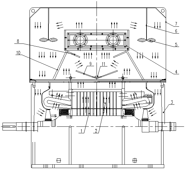
[0020] The specific embodiment of the present invention is described in detail below in conjunction with accompanying drawing, figure 1 The arrows in indicate the direction of the airflow.

[0021] Such as figure 1 As shown, a novel air-water cooler structure for a high power density box-type motor of the present invention includes a cooler installed above the motor frame 3, the motor frame 3 has a stator 2 and a rotor 1, and the motor frame 3 The top is provided with an air outlet hole and an air inlet hole connected to the cooler. The cooler includes a cooler housing 7. The bottom of the cooler housing 7 is provided with an air inlet corresponding to the air outlet hole. The cooler The bottom of the housing 7 is provided with an air outlet corresponding to the air inlet; the inside of the cooler housing 7 is located above the air inlet, and a cooling pipe group 4 is pierced, and the cooling pipe group 4 is composed of cooling pipes arranged in an array. Composition, and th...


PUM


Abstract

The invention discloses a novel air-water cooler structure for a high-power-density box motor. The novel air-water cooler structure comprises a cooler installed above a motor base. Air outlet and inlet holes connected with the cooler are arranged at the top of the motor base. The cooler includes a cooler housing. Air inlets are arranged at the bottom of the cooler housing and corresponding to theair outlet holes. Air outlets are arranged at the bottom of the cooler housing and corresponding to the air inlet holes. A cooling tube group is disposed inside the cooler housing and above the air inlets. The cooling tube group is composed of cooling tubes arranged in an array, and the cooling tubes are all arranged along a direction perpendicular to the axis of a motor shaft. Fin structures arearranged outside bodies of the cooling tubes. A cooling liquid flows in the bodies of the cooling tubes. An annular air guiding plate is arranged between the cooling tube group and the air inlets. Thenovel air-water cooler structure of the invention has the advantages of large heat dissipation capacity and high efficiency.

Description

technical field [0001] The invention belongs to the technical field of motor cooling, and in particular relates to a novel air-water cooler structure for a box-type motor with high power density. Background technique [0002] At present, domestic box-type motor ventilation systems mostly use air-to-air coolers, relying on external fans or forced fans to provide air power sources, resulting in an increase in the number of forced fans, high manufacturing costs, and high energy consumption, which affects the energy-saving effect of the motor. The external wind path is limited by the structure of the motor, the utilization rate of wind energy is low, and most of the wind energy is dissipated in the atmosphere as kinetic energy. [0003] The existing air-water cooler is limited by the type of cooling structure. The air-water cooler is mostly used in the ventilation system of the symmetrical air path structure of the motor, and the cooled air inside the cooler reduces the flow spe...

Claims


Application Information

Patent Timeline
Patent Type & Authority Applications(China)
IPC IPC(8): H02K9/04H02K9/12H02K9/19
CPCH02K9/04H02K9/12H02K9/19
Inventor 王晓俊赵强赵现伟冯婵蒋娟韦翠翠刘平顺张道洋牛朝阳蔡合超包猛羊娟
Owner WOLONG ELECTRIC GRP CO LTD
Learn More