Method for producing an extruded pressed screen and corresponding screen

A technology of punching grids and pressure, which is applied to the parts of connecting devices, the assembly/disassembly of contacts, electrical components, etc., to achieve the effect of reliable process flow and good positioning

Inactive Publication Date: 2007-04-11
ROBERT BOSCH GMBH
View PDF0 Cites 8 Cited by
  • Summary
  • Abstract
  • Description
  • Claims
  • Application Information

AI Technical Summary

Problems solved by technology

However, the use of punches results in the stamped grill not being covered with plastic at these anchor points, which can be detrimental under harsh environmental conditions to which the metal of the stamped grill is exposed

Method used


Image

  • Method for producing an extruded pressed screen and corresponding screen
  • Method for producing an extruded pressed screen and corresponding screen
  • Method for producing an extruded pressed screen and corresponding screen

Examples


Embodiment Construction

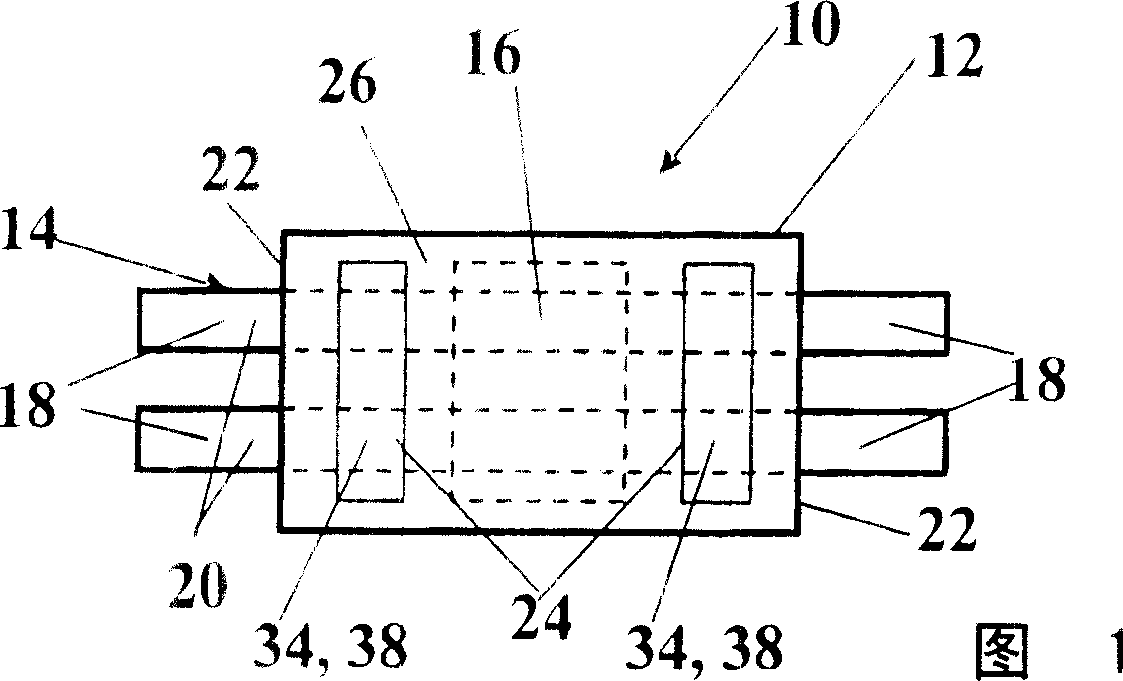
[0020] FIG. 1 shows a bottom view of an interference suppression device 10 for an electric motor (not shown). The interference suppression device 10 comprises a plastic housing 12 and an embedded punched grid 14 on which a capacitor 16 is arranged, which capacitor is optionally connected to a resistor. The interference suppression device 10 has four ports 18 which are formed by two parallel strips 20 of the stamped grid 14 which protrude from the housing 12 on two opposite longitudinal sides 22 . Instead of the simpler interference suppression device 10 , it is also conceivable to provide a complex controller with a plurality of interfaces 18 and a significantly more complex stamped grid 14 , which carries a number of different components instead of just the capacitor 16 . It is of course also possible to provide no electronic components, but only an injection-molded punched grid 14 , for example in the form of a plug. Preferably, however, the electronic components are arran...


PUM


Abstract

The invention relates to a method for producing an extruded pressed screen (14) on which components (16) are arranged, said screen being coated in plastic (26) in an injection mould (40). The inventive pressed screen (14) is fixed to a fixing point (28, 34) during the injection moulding process by means of a fixing element, such that the form thereof is maintained during said process. Said fixing element is a plastic element (38) which is coated by the injected plastic (26) in such a way that it seals the fixing point (28, 34). The invention also relates to an extruded pressed screen (14) that is inserted into a plastic housing (12) comprising a first and a second component (24, 26). Said pressed screen (14) is entirely coated with the second component (26), with the exception of the terminals (18) for the mechanical and / or electrical connection of the pressed screen (14). The first component (24) ends on a first outer side (30) and a second outer side (32) of the housing (12).

Description

technical field [0001] The invention relates to a method for producing an extrusion-molded punched grille according to the preambles of independent claims 1 and 8 and to an extrusion-molded punched grille on which preferably electronic components are arranged. Background technique [0002] In a known method, the stamped grid is embedded in a plastic injection mold. During the injection molding process, the stamped grid is usually positioned at several positioning points using positioning elements. The positioning element is a punch, which is arranged in the injection mold and fixes the punching grid in pairs. This fixes the stamped grid in its mold so that the shape of the stamped grid remains substantially unchanged during the injection molding process. However, the use of punches results in the stamped grid not being covered with plastic at these anchor points, which can be detrimental under harsh environmental conditions to which the metal of the stamped grid is exposed...

Claims


Application Information

Patent Timeline
Patent Type & Authority Applications(China)
IPC IPC(8): H01R43/24B29C45/14H01R13/405
CPCH01R13/405H01R43/24
Inventor M·霍尔贝尔特
Owner ROBERT BOSCH GMBH
Why Eureka
Try Eureka