
LED energy saving lump

A technology of LED energy-saving lamps and LED light sources, applied in the direction of lamp shades, cooling/heating devices of lighting devices, lighting and heating equipment, etc., can solve the problem of limiting the brightness and application range of lamps, unable to meet high-power LED heat dissipation, and unable to use high-power LED and other problems, to achieve the effect of slow light attenuation, improved service life, and good heat dissipation effect

Inactive Publication Date: 2007-04-18
诸建平
View PDF1 Cites 22 Cited by
  • Summary
  • Abstract
  • Description
  • Claims
  • Application Information

AI Technical Summary

Problems solved by technology

Apparently, this patent does not take into account the heat dissipation of LEDs. The circular heat dissipation holes under the lamp holder alone cannot satisfy the heat dissipation of high-power LEDs. Therefore, LEDs can only be low-power LEDs, and high-power LEDs cannot be used. Improve the brightness and range of use of lamps and lanterns

Method used


Image

  • LED energy saving lump
  • LED energy saving lump
  • LED energy saving lump

Examples


Embodiment 1

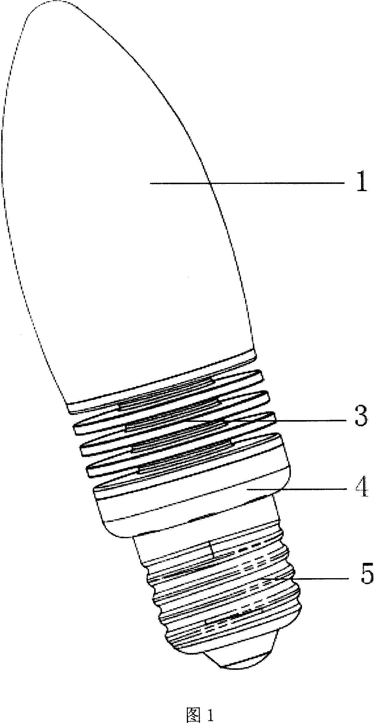
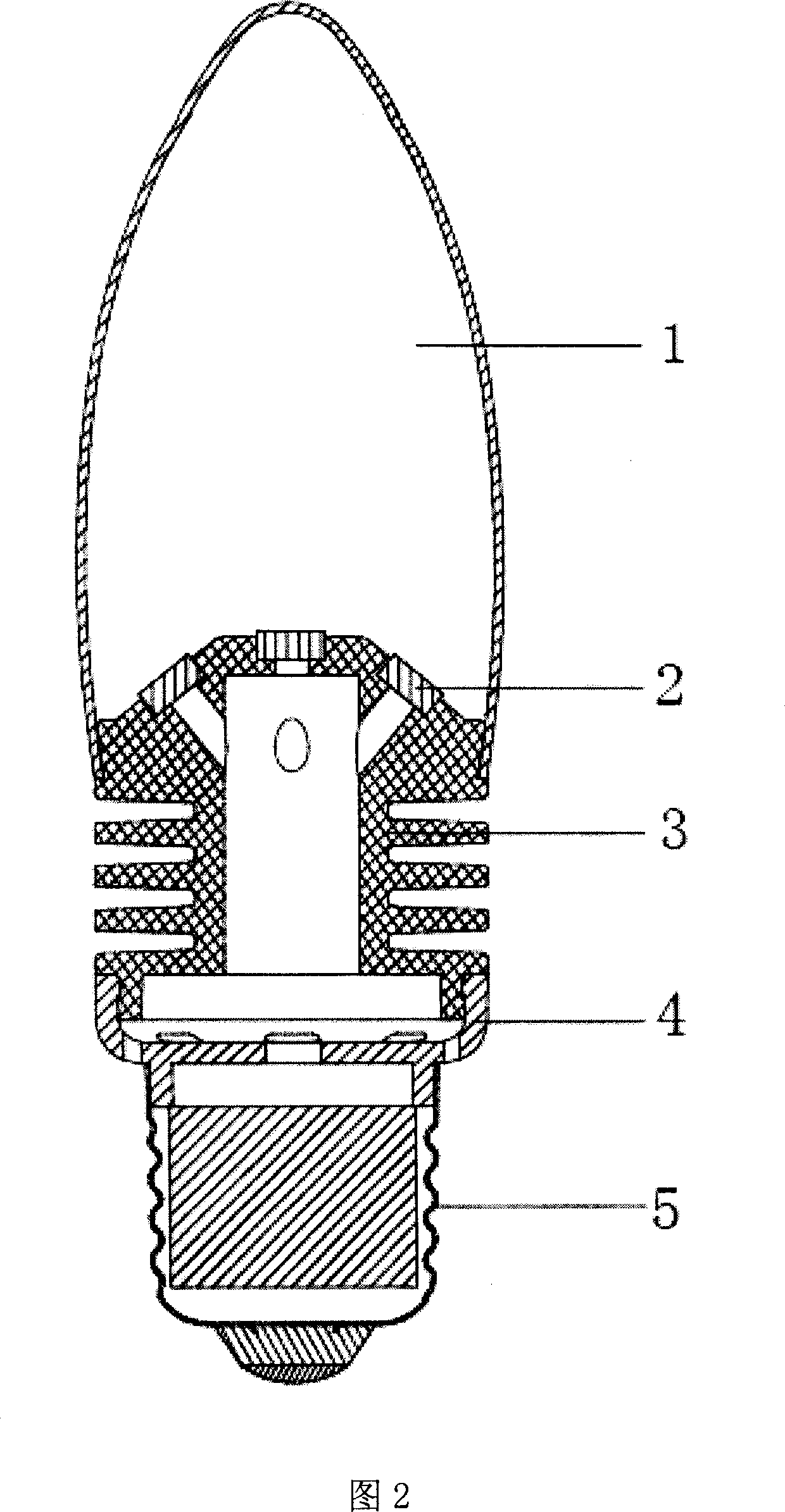
[0024] As shown in FIGS. 1 , 2 , 3 , and 4 , this embodiment consists of a lampshade 1 , an LED light source 2 , a radiator 3 , an insulator 4 and a lamp holder 5 . Wherein as shown in Figure 3, the port portion of the lampshade 1 is provided with an inner buckle 12, and the place below the surface 31 of the radiating body 3 is provided with an outer buckle 35, which together with the inner buckle 12 constitutes an inverted connection structure, the lampshade 1 It is fixedly connected with radiator 2. Similarly, as shown in Figures 3 and 4, the other open end of the heat sink 3 is provided with an inner buckle 37, and the insulator 4 is provided with an outer buckle 41, both of which form an inverted connection structure, and the heat sink 3 and the insulator 4 connections are fixed. And one end of the insulator 4 is bonded to the inner wall of the lamp holder main body 51 through a silicone material, and then fixed together by punching. Thus a complete lamp structure is for...

Embodiment 2

[0027] As shown in FIGS. 5 and 6 , the embodiment consists of a lampshade 1 , an LED light source 2 , a radiator 3 , an insulator 4 and a lamp holder 5 . But the cooling fins 34 of its cooling body 3 are vertically distributed. As can be seen from Figures 7 and 8, an internal thread 37 is provided in the middle hollow cylinder 36 of the cooling body 3, and an external thread 41 is provided on the insulator 4. The radiator 3 and the insulating member 4 are connected and fixed.

[0028] In addition, the lampshade 1 and the radiator 3 can also be connected by other methods such as threaded structure, silicone adhesive or silicone adhesive and then punched and fixed; the radiator 3 and the insulating part 4 can also be connected by an inverted connection structure, silicone adhesive or other methods such as silicone bonding and then stamping and fixing; the insulator 4 and the lamp holder 5 can also be connected by other methods such as threaded structure, reverse buckle connectio...


PUM


Abstract

An energy-saving lighting lamps and lanterns, especially a LED energy-saving lamp consists of a lampshade, an LED light source, a cooling body, an insulating piece and a lamp holder. The LED light source is inlaid on the round-table-like surface at the end of the cooling body and the round-table-like surface is coated with a reflecting layer. In the centre of the cooling body there is a hollow column, around which are uniformly distributed metal cooling fins. LED can let the heat out effectively through an integral cooling body. The insulating piece is used for separating the cooling body from the lamp holder to insulate the cooling body. The lampholder includes a lampholder casing and an LED drive power source mounted in the lampholder casing.

Description

technical field [0001] The invention relates to an energy-saving lighting fixture, in particular to an LED energy-saving lamp. Background technique [0002] In the current situation of increasing global energy shortage, countries are advocating energy saving and looking for various ways to save energy. Among them, LED (light emitting diode) is due to its energy saving, environmental protection, long life, low driving voltage, high luminous efficiency, no radiation, and The impact and other advantages have attracted much attention. [0003] In the market, there are already various LED lamps with uneven quality, and most of them have problems such as insufficient brightness, limited power, poor heat dissipation effect, fast light attenuation, and high cost. [0004] In the Patent Publication No. CN1407271A for the invention patent of LED chip fluorescent energy-saving lamp, the LED is embedded on the wick column in the lampshade, and the LED is driven to emit light by the dri...

Claims


Application Information

Patent Timeline
IPC IPC(8): F21S6/00F21V29/00F21V19/00F21V3/04F21Y101/02
CPCF21V3/0481F21Y2101/02F21V3/04F21V29/2225F21K9/135F21V29/2243F21Y2111/007F21K9/232F21V3/12F21V29/76F21V29/77F21Y2107/40F21Y2115/10
Inventor 诸建平
Owner 诸建平
Learn More