Mounting structure of air separation device and gas turbine containing same

An air separator and installation structure technology, applied in the direction of machines/engines, mechanical equipment, engine components, etc., can solve the problems of air leakage, easy vibration of air separators, etc., to prevent air leakage, improve sealing effect, and improve sealing effect of effect

Inactive Publication Date: 2007-04-25
MITSUBISHI HEAVY IND LTD
View PDF1 Cites 1 Cited by
  • Summary
  • Abstract
  • Description
  • Claims
  • Application Information

AI Technical Summary

Problems solved by technology

That is to say, when the temperature of the flange portion decreases, the contact surface of the flange portion and the rotating blade rotating disk moves toward the center of the radius relative to each other due to the difference in heat shrinkage in the contact surface, and the reduction of the bolt tightening force occurs at the same time. The contact surface is prone to air leakage
That is, in the case of such a sudden temperature change accompanying hot start operation, there is a problem that air leakage is likely to occur in the contact surface between the flange portion and the rotor blade rotary disk when the method of sealing by bolt tightening force is adopted, and the air is separated. are also prone to vibration

Method used


Image

  • Mounting structure of air separation device and gas turbine containing same
  • Mounting structure of air separation device and gas turbine containing same
  • Mounting structure of air separation device and gas turbine containing same

Examples


Embodiment Construction

[0045] The best mode for carrying out the present invention will be described below with reference to the accompanying drawings.

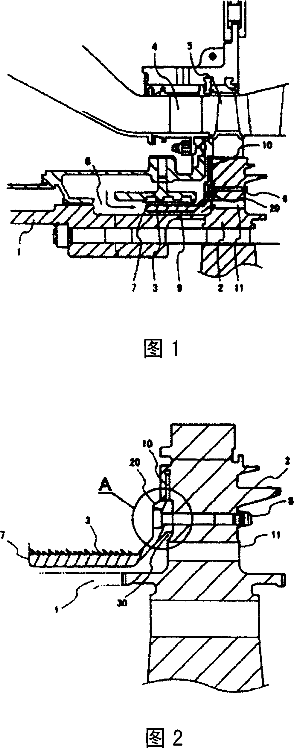
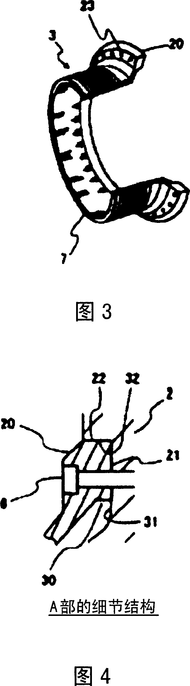
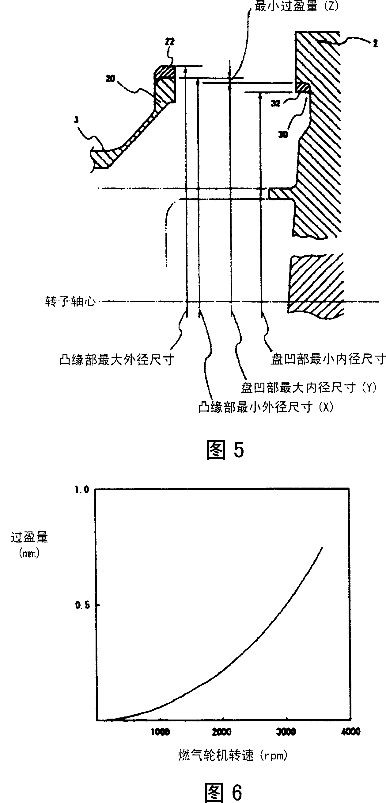
[0046] It only represents an embodiment of the present invention, and is limited to the structures involved in the present invention, not limited to this embodiment, and there are also similar methods. Fig. 1 is the overall structure of the air separator of the gas turbine of the present invention, Fig. 2 is a structural diagram around the installation structure of the air separator of the present invention, Fig. 3 is a perspective view of the air separator involved in the present invention, and Fig. 4 is an air separator of the present invention The details of the installation structure around the flange part, Figure 5 is the matching relationship between the flange part and the disc recess, Figure 6 is the interference relationship between the flange part and the disc recess due to the turbine speed and centrifugal force during the start-up operat...


PUM


Abstract

The invention provides an installing structure for air separator. The installing structure is cylinder part connected to the gap of opening, which is relative to rotor peripheral face. It comprises air separator, of which flange part is set on one end; and rotating disc for rotating vane, of which disc dent is set on the outer surface. The disc dent is circular with said rotor shaft as the center and sealing face is formed on the contacting face between outer peripheral face of the flange part and inner peripheral face of the disc dent part relatively. Said outer peripheral face of the flange part is set on said flange part and parallel to the shaft core of said rotor. Said inner peripheral face of disc dent part is set in said disc dent part, parallel to the shaft core of said rotor and is circular by the shaft core as center. In this way, cooling air is provided to rotating vane of gas turbine engine stably.

Description

technical field [0001] The present invention relates to a mounting structure of an air separator for supplying cooling air to rotor blades of a gas turbine. Background technique [0002] The installation structure of the air separator includes the air separator and the rotor blade rotating disk, and as cooling air for the rotor blade of the gas turbine, a part of compressed air from the compressor is used for supplying the cooling air to the rotor blade. [0003] Fig. 8 shows the overall structure of a gas turbine around a conventional air separator. For example, as shown in Japanese Patent Laid-Open No. 11-013408, the high-temperature exhaust gas discharged from the combustor 40 of the gas turbine passes through the first-stage fixed blades 4 and the first-stage rotating blades 5, and then passes through the latter-stage fixed blades and rotating blades. The high-temperature energy contained in the exhaust gas is converted into the rotational energy of the gas turbine and ...

Claims


Application Information

Patent Timeline
Patent Type & Authority Applications(China)
IPC IPC(8): F01D9/06F01D5/06F02C7/18
Inventor 兼泽佳行寺崎正雄
Owner MITSUBISHI HEAVY IND LTD
Why Eureka
Try Eureka